


9
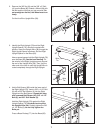
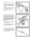
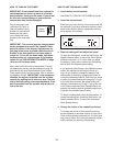
8. Insert the indicated connectors into the Right
Upright (78).
Next, insert the fronts of the brackets on the
B
ridge (95) into the Uprights (74, 78), and then
fully insert the brackets. Make sure that the
plastic edges of the Bridge are inside the
Uprights.
Attach the Bridge (95) with six 1/4" x 1/2" Bolts
(7) and six 1/4" Star Washers (10); start all six
Bolts before tightening any of them.
See steps 4 and 6. Tighten the four 3/8" x 4 1/2"
Bolts (6).
10
7
95
Connectors
Front
Edge
74
78
10
7
7
7
8
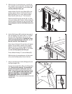
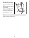
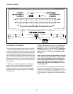
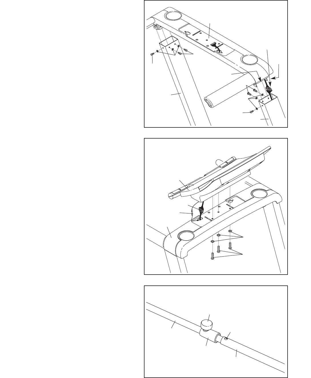
9. Have a second person hold the console assem-
bly near the Bridge (95). Connect the Bridge
Wire (52) to the console assembly wire. See the
inset drawing in step 7. The connectors
should slide together easily and snap into
place. If they do not, turn one connector and try
again. IF THE CONNECTORS ARE NOT CON-
NECTED PROPERLY, THE CONSOLE MAY
BE DAMAGED WHEN THE POWER IS
TURNED ON.
Connect the Console Ground Wire (101) to the
console assembly ground wire. Insert the wires
into the console assembly.
Attach the console assembly with three 3/8" x
1 1/4" Bolts (5) and three 3/8" Star Washers (9).
Be careful not to pinch the wires.
Console
Assembly
52
101
95
5
9
9
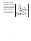
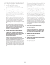
10. Identify the Storage Latch (53). Remove the tie
from the end of the tube. Make sure that the
sleeve has been slid over the indicated hole and
that the Latch Knob (54) is locked into the indi-
cated hole. Pull on the sleeve to make sure
that it is locked into place.
54
Sleeve
Hole
Tube
53
10