


9
77
90
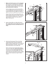
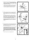
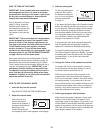
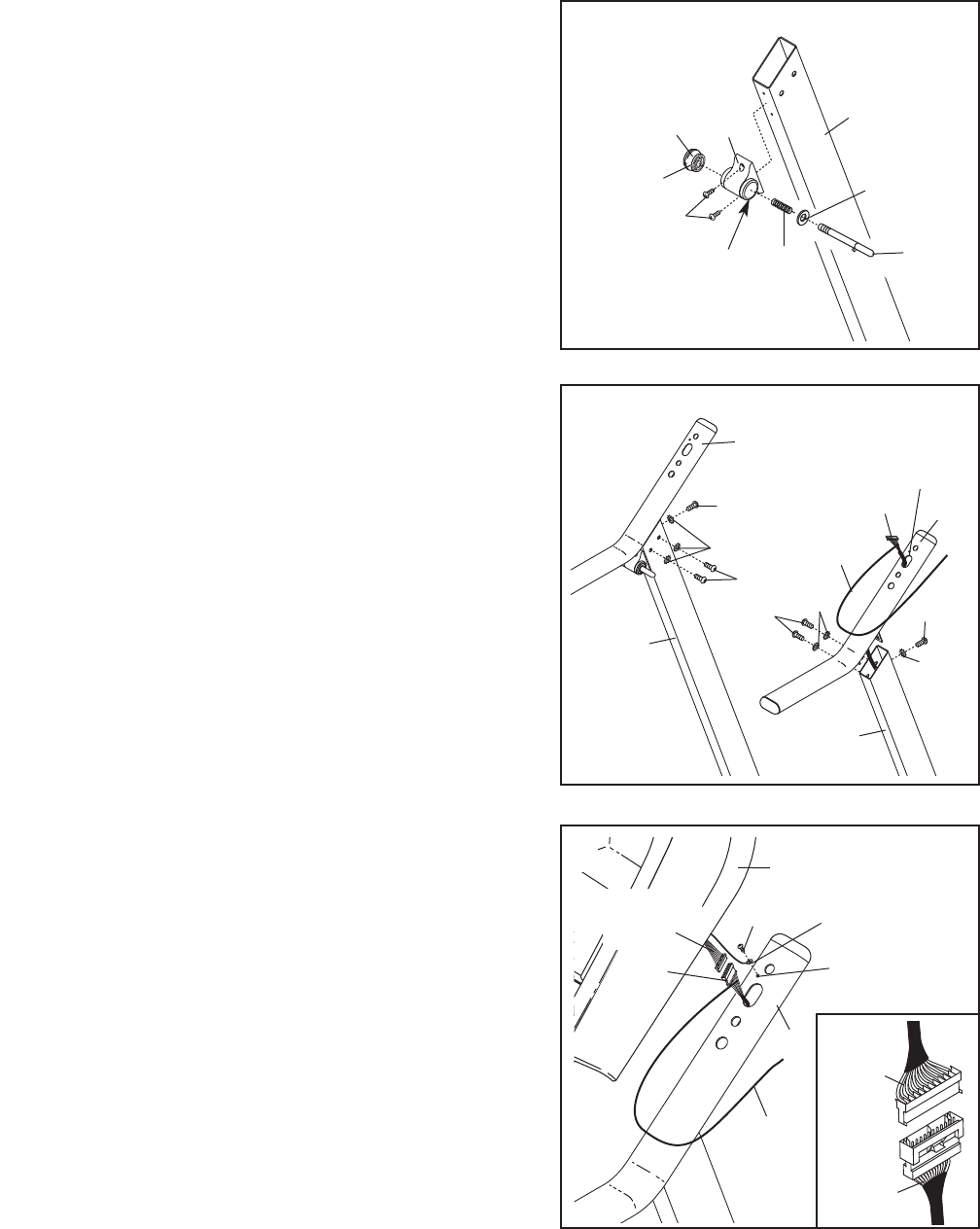
9. Have another person hold the console assembly near the
Right Handrail (90). Attach the end of the ground wire to
the indicated small hole in the Right Handrail with the
M4.2 x 13mm Silver Screw (4).
Connect the Upright Wire (77) to the console wire. See
the inset drawing. The connectors should slide to-
gether easily and snap into place. If they do not, turn
one connector and try again. IF THE CONNECTORS
ARE NOT CONNECTED PROPERLY, THE CONSOLE
MAY BE DAMAGED WHEN THE POWER IS TURNED
ON.
Remove the wire tie from the Upright Wire (77).
4
Console Assembly
Ground
Wire
Wire
Tie
9
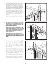
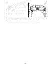
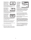
8. Hold the Right Handrail (90) near the Right Upright (78).
Insert the Upright Wire (77) into the opening in the bot-
tom of the Right Handrail and out of the indicated hole in
the top.
Set the Right Handrail (90) on the Right Upright (78),
and finger tighten three M8 x 19mm Bolts (6) with three
M8 Star Washers (10) into the Right Handrail and the
Right Upright. Do not fully tighten the Bolts yet. Make
sure that the Upright Wire (77) is not pinched.
Attach the Left Handrail (89) to the Left Upright (73)
as described above. Note: There are no wires on the
left side.
78
6
6
10
77
73
89
10
10
6
6
Wire Tie
90
8
77
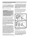
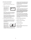
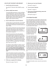
7. Attach the Latch Insert (70) to the Left Upright (73) with
two #10 x 1" Tek Screws (76). Make sure that the large
hole in the Latch Insert is on the side shown. Do not
o
vertighten the Tek Screws.
L
ocate the Latch Pin Assembly (72). Remove the knob
from the pin. Make sure that the collar and the spring
are on the pin as shown. Insert the pin into the Latch
Insert (70), and tighten the knob back onto the pin.
76
Console
Wire
70
7
3
7
K
nob
Pin
Collar
Spring
Large Hole
72
Hole
Small Hole
Console
Wire