10
28
18
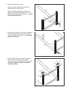
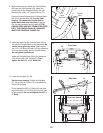
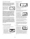
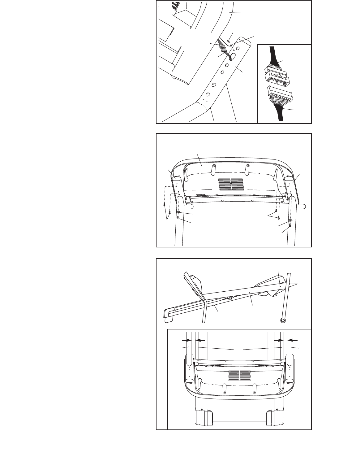
9. While another person holds the Console Base
(26) near the right Handrail (18), attach the
ground wire on the Console Base to the right
H
andrail with a #8 x 1/2" Ground Screw (11).
C
onnect the wire harness on the Console Base
(26) to the Upright Wire (28). See the inset
drawing. The connectors should slide to-
gether easily and snap into place. If they do
not, turn one connector and try again. IF THE
CONNECTORS ARE NOT CONNECTED PROP-
ERLY, THE CONSOLE MAY BE DAMAGED
WHEN THE POWER IS TURNED ON.
11
2
6
Ground
Wire
28
Wire
H
arness
9
22
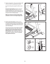
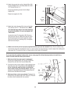
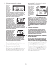
10. Insert the wires into the Console Base (26) as
you set the Console Base on the Handrails. Be
careful not to pinch the wires. Next, thread
two 1/4" x 1/2" Bolts (22) with 1/4" Star Washers
(21) into the Handrails and the Console Base;
do not tighten the Bolts yet.
Attach the Console Base (26) to the Handrails
(18) with four #8 x 3/4" Screws (2). Then,
tighten the two 1/4" x 1/2" Bolts (22).
2
22
21
21
2
18
18
10
26
Front View
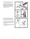
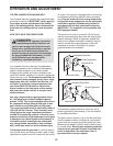
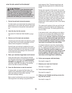
11. Lower the Uprights (31, 36).
See the inset drawing. Position the Uprights
(31, 36) so that the Frame (74) is centered be-
tween the Uprights.
Firmly tighten the 3/8" x 3" Bolts (32) and then
tighten the 3/8" x 2 1/4" Bolts (40) on each side
of the treadmill. Do not overtighten the 3/8" x
3" Bolts.
36
31, 36
32
74
74
31
View from Above
Side View
11
40
Wire
Harness


