


12 13
GB
GB
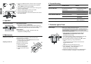
If you connect several Irrigation Valves to one water supply, then
each pipe must be flushed separately in order to obtain an ade-
quate flushing pressure. To do this:
1. Push the short telescopic pipe
A
into the nipple on the inlet-
side
5
which is not to be flushed.
2. Push the bracket
0
into the elongated holes of the nipple on
the inlet-side
5
.
The short telescopic tube
A
is fixed in place.
3. Screw the end cap
B
onto the short telescopic pipe
A
.
The integrated solenoid valve only works correctly with the
Irrigation Valve connected in flow direction.
Flow direction
A V Pay attention to the flow direction (arrows) when
assembling the Irrigation Valve
C
.
1. Push the long telescopic pipe
8
all the way into the nipple
on the outlet-side
5
a.
2. Screw the short telescopic pipe
A
into the inlet side of the
Irrigation Valve
C
.
The arrows on the Irrigation Valve point in the flow direction.
3. Push the short telescopic pipe
A
into the nipple on the inlet-
side
5
.
4. Screw the long telescopic pipe
8
into the outlet-side of the
Irrigation Valve
C
.
5. Push the bracket
0
into the elongated holes of the nipples
5
/
5
a.
The telescopic pipes
8
/
A
are fixed in place.
When you open the box lid
D
you can see the flow direction
marked by the arrows on the Irrigation Valve
C
.
v The box lid
D
can be locked by turning the lever
E
by 90°.
The box lid
D
can be locked as a protection against theft.
v Overlap the holes
F
of the valve box and the box lid and lock
using a small padlock
– or –
alternatively, the lid
D
can be safeguarded against theft using
a sheet metal screw (4.2 x 19).
In conjunction with the programmed watering time, the moisture
level of the soil or the natural precipitation can be taken into
account for each Irrigation Valve.
When a sufficient moisture content of the soil is reached, a pro-
gramme may be interrupted or activation of a programme may
be suppressed.
Close off nipple
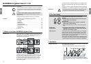
on inlet-side:
Assemble the
Irrigation Valve:
Lock the box lid:
Connect Soil Moisture
Sensor or Rain Sensor
electronic (optional):
B
A
0
5
E
F
D
z
5a
0
A C 85
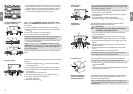
Connect GARDENA connect-
ing pipes to valve box:
Flash the system:
2. For underground installation, place a layer of course gravel
1
approx. 20 x 30 x 10 cm
3
(V1) / 30 x 35 x 10 cm
3
(V 2) under-
neath the valve box.
This ensures proper drainage of the box.
3. Install the valve box with the top edge of the box at ground
level.
This avoids damage when mowing the lawn.
You can use the GARDENA Connecting Pipe Art. No. 1580/
1582
3
and GARDENA Hose Clips Art. No. 1591
2
to connect
the valve box.
1. Push the nipples
5
from the inside into the box openings.
2. Fasten the nipples
5
to the valve box from the outside using
the nuts
6
.
3. Screw a tap connector
4
on each nipple
5
.
4. Push a hose clip
2
over each pipe end
3
.
Tip: Place the pipe ends
3
in warm water to make it easier to
push the ends of the pipes
3
onto the tap connectors
4
.
5. Push the connecting pipes
3
onto the tap connectors
4
and
secure with the hose clips
2
.
Note: You can also attach a GARDENA Connector Art. No.
2745/ 2749
7
(1
"
= 25 mm / 5/4
"
= 32 mm) to the nipples
5
for
connecting hard connecting pipes or other commercially avail-
able connecting pipes.
After connecting the pipes to the valve box, the system must be
flushed.
Flushing the system after routing the pipes prevents contaminating
the valves.
1. Push the long telescopic pipe
8
all the way into the nipple
on the outlet-side
5
a.
2. Push the flushing pipe
9
into the nipple on the inlet-side
5
.
3. Push the bracket
0
into the elongated holes of the nipple on
the inlet-side
5
.
The flushing pipe
9
is fixed in place.
4. Screw the long telescopic pipe
8
onto the flushing pipe
9
.
5. Turn on the water supply at the nipple
5
.
The system is flushed.
6. Remove the flushing pipe
9
.
1
1
z
5a
0
5 9 8
2 3 4
4
4
5
5
6
6
6
6
77