


FE46 Elliptical
8
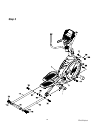
STEP 1: CONSOLE MAST ASSEMBLY
1. Locate the Console Mast (10) and Console Mast Cover (41) and slide the Cover onto the
Mast as far as it will go. Make sure the Console Mast Cover (41) is facing the correct
way.
2. At the top opening of the Main Frame (1), there is a Computer Cable (32) tied with a
guiding wire. Unravel the wire and feed the Computer Cable (32) it into the bottom of the
Console Mast tube (10) and out of the top opening.
3. Install the Console Mast (10) into the receiving bracket on the top of the Main Frame (1).
Pull slightly on the computer cable at the top of the mast while installing. This will ensure
the cable does not get pinched and shorted during mast assembly.
4. Install one 3/8" x 2T Split Washer (120) and one 3/8 x 23 x 2T Curved Washer (114) onto
one of the 3/8" x 3" Hex Head Bolts (119) and install through the front of the Console
Mast. Install two 3/8 x 19 x 1.5T Flat Washers (94) and two 3/8" x 2T Split Washers (120)
onto two 3/8" x 3" Hex Head Bolts (119). Install them through the left side of the receiving
bracket into the Console Mast (10).
NOTE: The Computer Cable runs through the Console Mast tube. Be careful not to
damage or pinch this cable during this procedure as damage to the Console Assembly
could result.
5. Use the 13/14m/m Wrench (111) to tighten the three bolts firmly. These bolts should be
tightened as much as you possibly can. Snap the console mast cover into place.
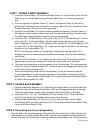
6. There are three connectors at the top opening of the Console Mast (10), two Hand pulse
wires (37) and one Computer Cable (32). Connect these to the mating connectors on the
back of the Console Assembly (31).
7. Store the excess wiring back into the Console Mast (10) as you carefully install the
Console Assembly (31) onto the mounting plate of Console Mast. Secure the console
with four M5 x 10m/m Phillips Head Screws (78) by using Combination M5 Allen Wrench
& Phillips Head Screw Driver (108).
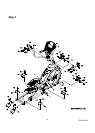
STEP 2: HANDLE BAR ASSEMBLY
1. Install the two Wave Washers (101) onto the Left and Right sides of the Handle Bar axle.
2. Slide the Lower Left and Right Handle Bars (4&5) onto the appropriate side of the axle.
There is a small sticker on each lower handlebar that shows L (Left) or R (Right).
3. Install two 5/16" x 23 x 1.5T Flat Washers (97) onto the two 5/16" x 15mm Hex Head
bolts (70) and install in the threaded holes in the ends of the axle.
4. Install the two Handle Bars (13, left) and (14, right), onto the Lower Left and Right
Handle Bars (4&5) and fasten with three 5/16x 15m/m Button Head Socket Bolts (75) by
using the M5 Allen Wrench (108).
STEP 3: Connecting arm & rear rail assembly
1. Align the hole in the rod end bearings at the end of the Connecting Arms (7&8) with the hole
in the bracket of the Lower Handle Bars (4&5). There is a sleeve spacer already installed in
the rod ends and held in place with a twist tie; make sure these spacers do not fall out during