


FE46 Elliptical
9
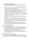
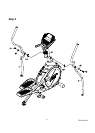
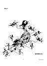
assembly. The rod end bearing should be positioned to the inside of the bracket on the Lower
Handle Bars. Install two 5/16" x 32m/m Hex Head Bolts (71) through the left and right Lower
Handle Bar brackets and the rod end. Install two 5/16" x 20 x 1.5T Flat Washers (98) and two
5/16" x 7T Nylon Nuts (105) on the 5/16" x 32m/m Hex Head Bolts (71) and tighten firmly by
using 12m/mWrench (110) and 13/14 m/m Wrench (111).
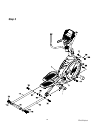
2. Install the two Rear Rail Tubes (16) with rear end of the Main Frame (1) and secure with two
3/8 x 2-1/4 Button Head Socket Screws (76), two 3/8 x 19 x 1.5T Flat Washers (94) and two
3/8 x 7T Nylon Nuts (89) by using 13/14 mm Wrench (111) and M5 Allen Wrench (108).
3. Install the Rail Stabilizer (15) between the rear end of the Rail Tubes (16) and secure with
four 3/8 x 2-1/4 Button Head Socket Screws (76) and 3/8 x 23 x 2T Curved Washers (114)
by using the M5 Allen Wrench (108).
STEP 4: Beauty covers assembly
1. Install the Connecting Arm Covers (59 & 60) over the connection of the rod end and
Lower Handle Bars (4 & 5) with four M5 x 15m/m Phillips Head Screws (79) and two
3.5x12m/m Self Tapping Screws (84) by using the Phillips Head Screw Driver (108).
2. Install the two Wheel Covers (52) on the pedal arms above the Wheels with the four
M5x15m/m Phillips Head Screws (79).
3. Install the Front Handle Bar Covers (54 & 56) and Rear Handle Bar Covers (55 & 57)
over the Handle Bars axle connections with the six 3.5x12m/m Self Tapping Screws
(84).
4. Install the two Middle Stabilizer Covers (61) on the joint of the Rail Tubes (16) and the
Stabilizer. Secure the covers with two M5 x 15mm Phillips Head Screws (79).
5. Install the Rear Stabilizer Covers (62 & 63) on the rear end of the Rail Tubes (16) and
secure them with two M5 x 15mm Phillips Head Screws (79).
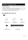
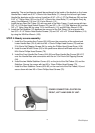
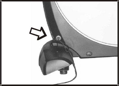
POWER CONNECTOR LOCATED ON
FRONT, LEFT HAND SIDE OF UNIT.