


7
1 1 5 0 S E R I E S O W N E R’S M A N U A L
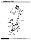
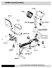
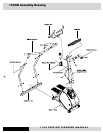
1150Rb Assembly Instructions
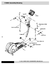
Rear Stabilizer Bar Assembly
1. Unscrew two M8x20mm bolts from the rear stabilizer bar.
2. Place rear stabilizer bar under rear mainframe body and align
screw holes.
3. Insert and tighten the two screws and washers using an Allen
wrench.
Seat Frame Assembly
1. Install the seat frame handlebar onto the seat frame. Insert
and tighten four M8x15mm screws and washers using an Allen
wrench.
2. Install seat pads on the seat frame using M6 x 55mm screws
and washers, (four for each pad) and a Phillips screwdriver.
3. Remove the hand pulse harness, which is stored next to the front
end of the seat track. Assemble seat frame to seat track. Be
careful not to cut the hand pulse harness during installation.
SEAT FRAME INSTALLATION HINT: Pull the seat-frame ad
-
justing handle up then slide the seat frame onto seat track.
After the sliding, find a position and release the adjusting
handle to lock the seat frame in position.
4. Adjust both nuts, located in the middle of seat frame, to ensure
the seat frame is stable, not waddling. Note: always come back
and adjust these two nuts after a period of time, this way, it will
ensure the seat frame remains stable all the time.
5. Assemble seat frame Stop by sliding the washers and rubber
ring onto M8x40mm bolt and insert and tighten it with an Allen
wrench into the Right side of AL seat track. Insert and tighten a
M8x20mm screw and a washer into Left side of AL seat track
with an Allen wrench to secure the seat frame.
6. Assemble seat track end cap onto seat track. Insert and tighten
M5x12mm screw using a Phillips screwdriver to secure the end
cap.
7. Bring the hand pulse harness connector through the back of the
seat frame and plug it into the plug receptor outside of the seat
handlebar. Secure harness by securing it with ty-wrap onto the
side of seat frame.
Console Mast Assembly
1. Install console mast cover onto console mast, making sure it is
facing the right direction.
2. Straighten the loops of both wire harnesses and insert them
into the bottom opening of the console mast tube. See wiring
harness installation tip. Push the harness up the tube until the
connectors of the harnesses appear in the opening at the top of
the mast tube.
WIRING HARNESS INSTALLATION TIP: Straighten the loops
of the wire harness so that it can slide smoothly into the
console mast. Move the console mast cover all the way to
the top. Then hold the bottom of the console mast next to
the console mast receptor and point the top of the console
mast downward.
3. Install the console mast by sliding it into the console mast re
-
ceptor while pulling the wire harness. Insert and tighten four
M8x55mm Bolts using an Allen wrench.
4 Place console mast cover in place and align it with screw holes.
Insert and tighten four M5x12mm screws and washers using a
Phillips screwdriver.
Console Assembly
1. Connect both plugs, from main wire harness and hand pulse
harness, to the plug receptors on the backside of the console,
taking care to install correctly (see plug alignment marks).
WIRING HARNESS INSTALLATION TIP: Any excess wiring
must be carefully inserted (“stored”) back into the console
mast before installing the console onto the console mounting
plate.
2. Fasten the console to the console mounting plate with the four
M5x12mm screws and washers using a Philips screwdriver.
Handlebar Assembly
1. Place the handlebar onto the mount and insert and tighten two
M8x20mm screws using an Allen wrench. Note: The handlebar
can be installed upside down. When installed properly, the hand
grips align with the bottom of the console.
Pedals
1. Using a 15mm open-end wrench to firmly affix the pedals to the
cranks. The pedals should be tightened as much as possible
to prevent the pedals from becoming loose. The pedals should
also be checked after 8 hours of use to ensure they are affixed
properly as they can loosen after use.
2. The left and right pedals are different and are denoted as right
or left on the bottom of each pedal. NOTE: Left pedal threads
counter-clockwise.
Water Bottle
1. Place the bottle holder on the console mast. Insert and tighten
the two M5x12mm screws using a Phillips screwdriver.
2. Snap the water bottle into the holder.
Leveling Pad
1. Adjust all three leveling pads, located on the bottom of the
stabilizer bar and the main frame, to ensure your equipment is
leveled with floor.