14
Bowex
®
TreadClimber
®
Owner’s Manual
Assembly Guide
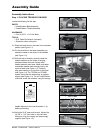
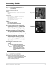
Figure 1-3
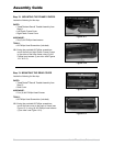
Figure 1-5
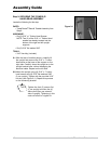
Figure 1-1
#!,,7)4(15%34)/.3
0/524/54%15%34)/.!00%,%:,%
ALIGN TO TREADLES
ALIGN TO UPRIGHT
BRACKET
FF2899
#!,,7)4(15%34)/.3
0/524/54%15%34)/.!00%,%:,%
ALIGN TO TREADLES
ALIGN TO UPRIGHT
BRACKET
FF2899
TREADLES
BRACKET
#!,,
7)4(15%34)/.3
0/524/54%15%34)/.!00%,%:,%
ALIGN TO TREADLES
ALIGN TO UPRIGHT
BRACKET
FF2899
Remove before use and follow these directions, “Before
tightening the bolts on the rear casting, center the treadles
using this card as a guide.”
Retirez avant l'emploi et suivez les ces directions, “Avant
serrant les boulon sur le bâti arrière, centrez les pédales en
utilisant cette carte comme guide.”
Illustration 1-A
Figure 1-2
Assembly Instructions
Step 1: PLACING TREADLES ON BASE
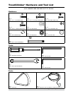
Locate the following for this step:
PARTS:
• TreadClimber
®
Base Assembly
• TreadClimber
®
Treadle Assembly
HARDWARE:
• Four (4) 3/8” x 1-1/4” Hex Bolts
TOOLS:
• 9/16” Open End Wrench (included)
• Scissors or other cutting tool
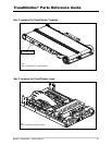
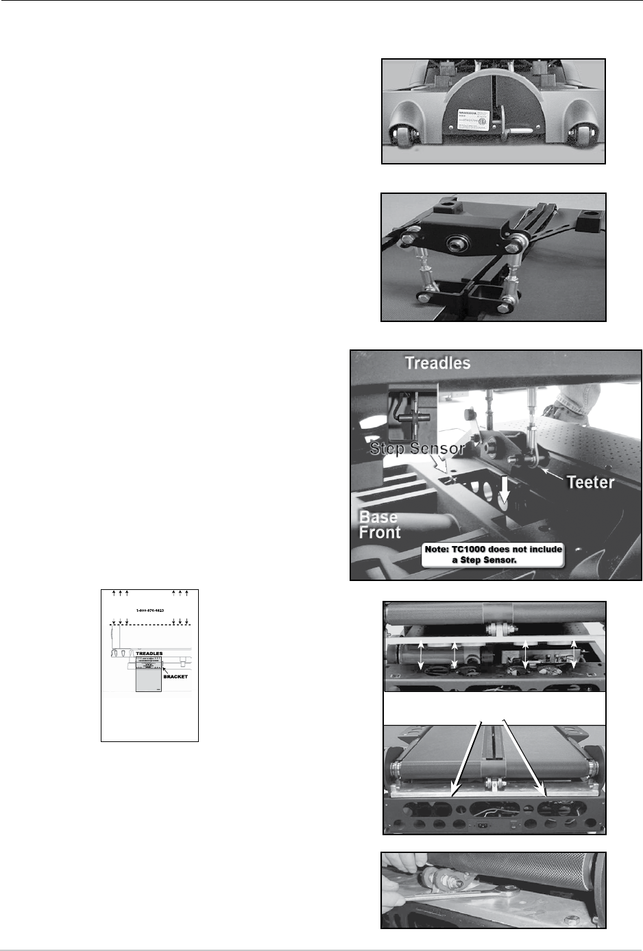
1-1 Place the latch lever on the base in the unlocked
position (see Figure 1-1).
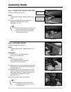
1-2 Cut the wire ties on the teeter assembly and
extend the teeter to the center of the treadles
(see Figure 1-2).
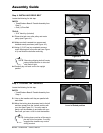
1-3 With the help of another, carefully rotate the
treadle assembly so the teeter is hanging
downward above the base. Slowly lower
treadle assembly onto base. Make sure teeter
mechanism passes freely through hole in the
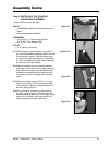
center of base (see Figure 1-3). Carefully
align roller casting so it lays flush on the base
(see Figure 1-4). For TC3000 and TC5000
models verify that the step sensor is properly
aligned (see Figure 1-3). For all TreadClimber
®
machines center the treadles, using the orange
treadle alignment card (see Illustration 1-A),
before proceeding.
1-4 Using the 9/16" open end wrench, tighten the
(4) 3/8" x 1-1/4" hex bolts on the rear roller
casting to bring the casting and base snugly
together (see Figure 1-5).
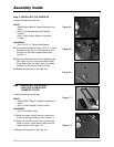
Figure 1-4
Align roller casting so it lays
flush on base


