14
13
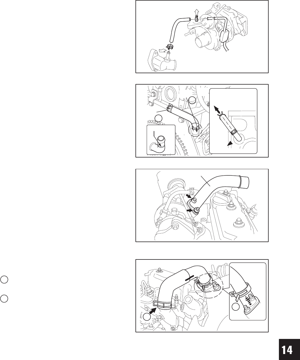
TURBOCHARGER
7. Install coolant outlet hose from turbocharger to
coolant inlet housing as shown, Fig. 36. Install
clamps with tabs as shown.
Fig. 36 – Install Coolant Outlet Hose
8. Install coolant inlet hose over inlet tube up to
yellow mark on tube. Install clamps with tabs as
shown.
Fig. 37 – Install Coolant Inlet Hose
A
YELLOW
MARK
B
9. Install air intake pipe.
a. Torque nuts to 13.0 Nm (115 in. lbs.).
Fig. 38 – Installing Air Intake Pipe
AIR INTAKE PIPE
10. Align the match marks (white paint), and install the
air intake hose onto the air intake pipe.
Installation direction of clamps:
A
Install the clamp so that tabs face rear of
engine.
B
Install the clamp so that tabs face out.
Fig. 39 – Installing Air Intake Hose
B
A


