40
Basic Operations of the Function Menu
Chapter 3 Preparations
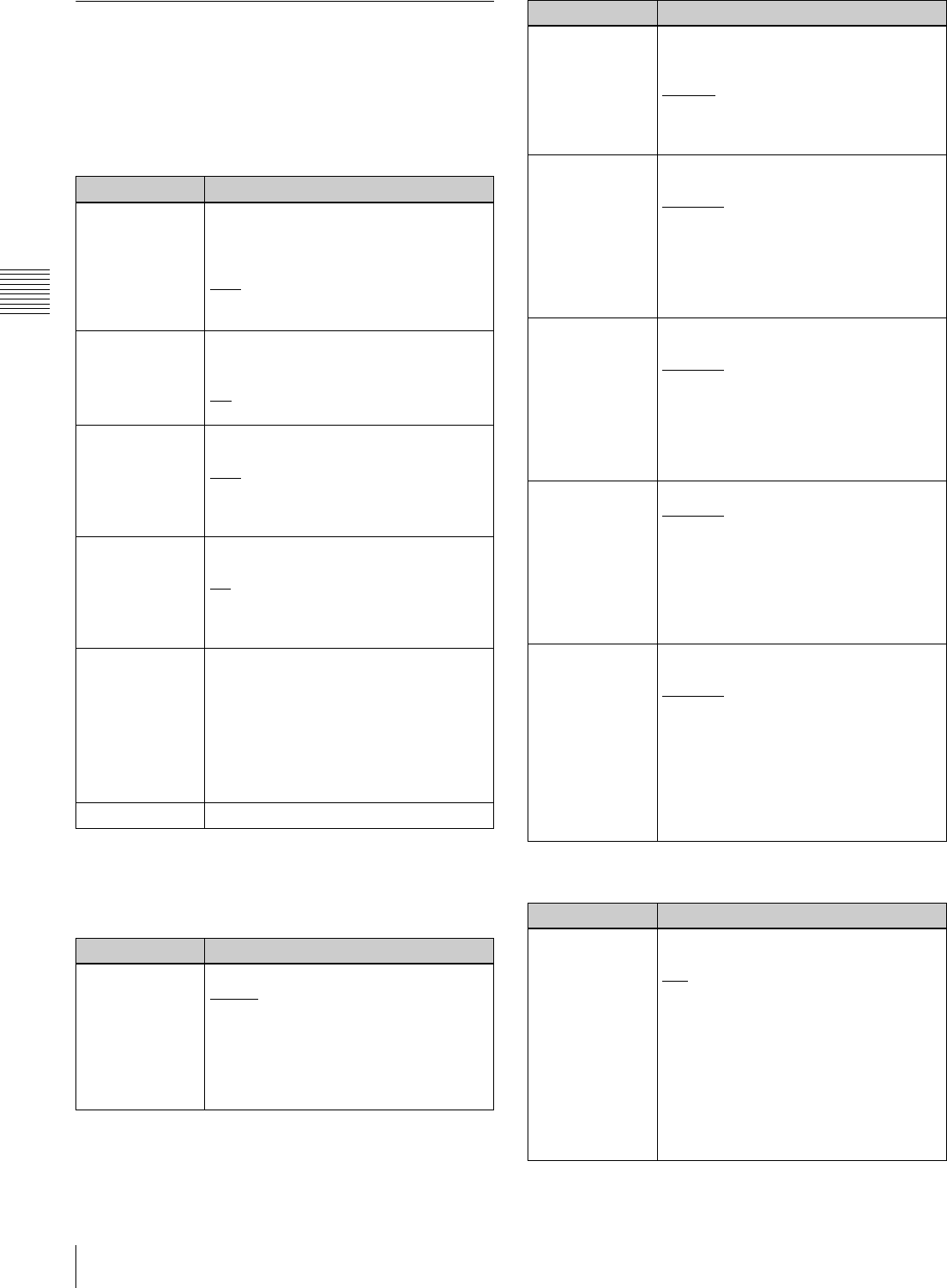
Function menu settings
The following tables list the setting items on each page and
describe their setting values. Underlined values are the
factory defaults.
HOME page
a) This is displayed only when TCG on page P4 TC of the function menu is
set to “INT”, and PRST/RGN is set to “PRESET”.
P1 VIDEO page
P2 AUDIO page
Item Setting
F1: CHAR SEL Turns the display of character
information on the color LCD and on an
external monitor on and off.
ON: Character information on
OFF
: Character information off
LCD: Character information on for the
color LCD only
F2: PB/EE Selects the type of video and audio
signals to output during fast forward, fast
reverse, stop, and standby.
PB
: Playback signal
EE: E-E signal
F3: REC INH Specifies whether to inhibit recording to
the disc.
OFF
: Do not inhibit recording.
ON: Inhibit recording to the disc
according to the setting of setup
menu item 310 REC INHIBIT.
F4: CNTR SEL Selects the type of time data to display in
the time data display area.
TC
: Timecode
COUNTER: Elapsed recording or
playback time
UB: User bits
F5: TCG SET • When CNTR SEL is set to “TC” ,
displays a screen where you can set
the initial value of the timecode
generated by the internal timecode
generator
a)
(see page 35)
.
• When CNTR SEL is set to “UB” ,
displays a screen where you can set
timecode user bits
a)
(see page 35)
.
F6: (Unassigned function button)
Item Setting
F1: V INPUT Selects the video input signal.
HDSDI
: HDSDI signal
i.LINK: i.LINK signal (when optional
board is installed)
SG: Test signal from internal signal
generator (Normally this item is not
displayed. It appears when you hold
the button down for 3 seconds.)
F2: VID. PROC Selects the method used to control the
internal video signal processor and make
related settings.
LOCAL
: Use the function menu to
change settings.
MENU: Use the setup menu to change
settings.
F3: VIDEO Sets the output level for HD/SD video
signals (range –∞ to +3 dB).
PRESET
: Set the video signal output
level to a preset value, regardless of
manual setting.
Manual setting: While the setting value
is flashing, turn the PUSH
SET(S.SEL) knob to adjust the video
signal output level.
F4: CHROMA Sets the output level for HD/SD chroma
signals (range –∞ to +3 dB).
PRESET
: Set the chroma signal output
level to a preset value, regardless of
manual setting.
Manual setting: While the setting value
is flashing, turn the PUSH
SET(S.SEL) knob to adjust the
chroma SETUP signal output level.
F5: HUE/CHRM
PHS
Sets the hue (chroma phase).
PRESET
: Set the hue (chroma phase) to
a preset value, regardless of manual
setting.
Manual setting: While the setting value
is flashing, turn the PUSH
SET(S.SEL) knob to adjust the hue
(chroma phase) over the range
±30°.
F6: SETUP/
BLACK
Sets the HD/SD output black setup level
or black level.
PRESET
: Set the level to the preset
value, regardless of the manual
setting.
Manual setting: While the setting value
is flashing, turn the PUSH
SET(S.SEL) knob to set the black
setup level (in 59.94i mode) over the
range ±30 IRE or the black level (in
50i mode) over the range ±210 mV.
Item Setting
F1: A1 INPUT Selects the audio input signal to assign
to audio channel 1.
SDI
: Audio signal embedded into SDI
signal
ANALOG1: Analog 1 audio signal
AES/EBU: Signal input to the DIGITAL
AUDIO(AES/EBU) IN 1/2 connectors
SG: Test signal from internal signal
generator (Normally this item is not
displayed. It appears when you hold
the button down for 3 seconds. The
test signal is assigned to audio
channels 1 to 8 simultaneously.)
Item Setting


