&_ickR_m_ce
Identifyingparts and controls
The nunlbers in / ) are reference pa_es.
[]
[]
%
[]
[]
[]
[]
[]
[]
[]
[]
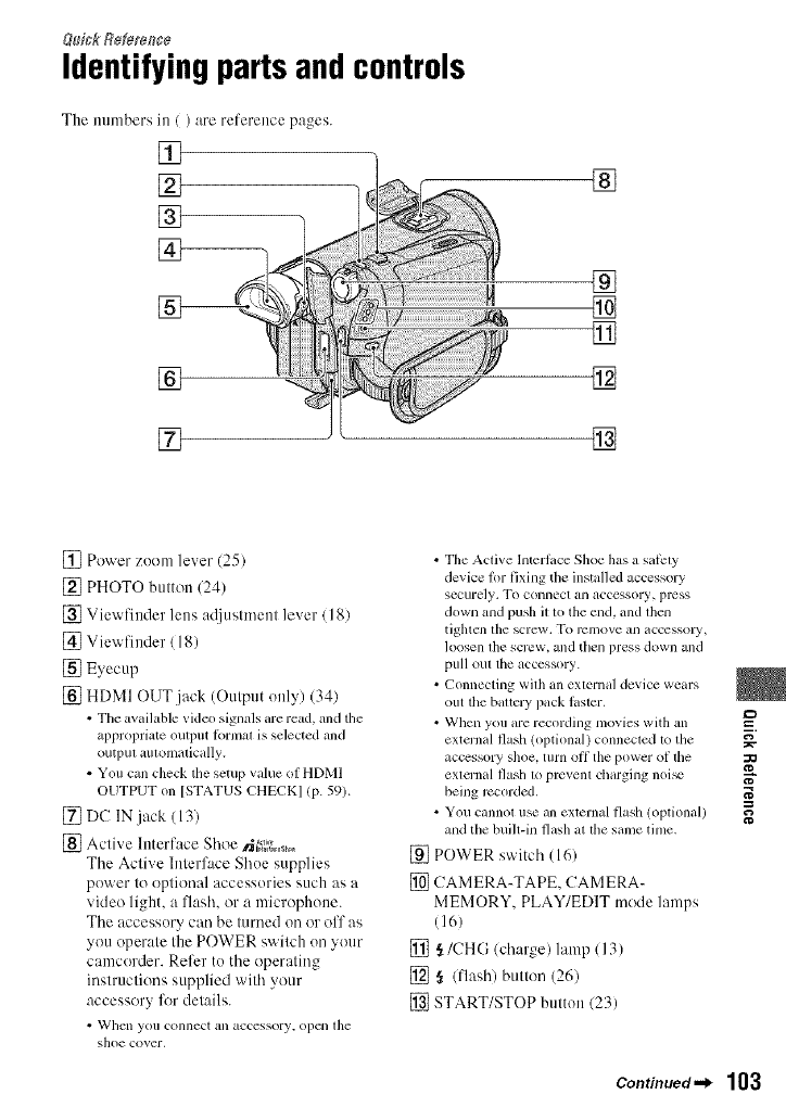
[] Power zuom lever (25)
[] PHOTO button (24)
[] Viewfiuder lens ac{iustn/eut lever / 18)
[] Viewfiuder/18)
[] Eyecup
[] HDMI OUT jack (Output only) (34)
• The available video signals are read, and the
appropriate output Ibrmat is selected and
outpul aulomalically.
• You call check the setup value of HDMI
OUTPUT on [STATUSCHECK] (P-59).
[] DC IN jack (13)
[] Active Interface Shoe _;,._s_0
The Active Interface Shue supplies
power to optional accessories such as a
video light, a flash, or a microphone.
The accessury can be turned on or off as
you operate the POWER switch un your
camcorder. Refer to the operating
instructions supplied with your
accessory lbr details.
• Whcll you c,onnect an acccssory, open lhe
shoe cover,
• TileActive Interlace Shoe has a salPty
device %rfixingthe installedaccessory
securely. To connect an acccssory, press
downand push illo the end,and lhen
tiglacn tile screw, To rc21Ilove all accessoly,
loosen lhe screw, and then press down all(]
pull out the accessory.
• Connecting with an external device wears
(lilt tile battery pack laster,
• Wllen you are recording movies with an
externalflash (optional) connecled1othe
accessory shoe,turn off the powerof the
exlernalflash 1oprcvenl charging noi_
beingrecorded,
• Youcannot use allexternalflasll (optional)
andthe built-in flashat lhe same tinle.
[] POWER switch (16)
[] CAMERA-TAPE, CAMERA-
MEMORY, PLAY/EDIT mode lamps
(16)
[] ,_/CHG/charge) lamp (13)
[] § (flash) button (26)
[] START/STOP button (23)
=_
o}
N"
g
Continued._ 103


