MODEL 158A 909GF197B
- 14 -
CALIBRATION PROCEDURE
4.3.1 Zero and Span Calibration
With the Model 158A Level-Tel mounted and
electrical connections made, the following
procedures should be followed in calibrating the
instrument:
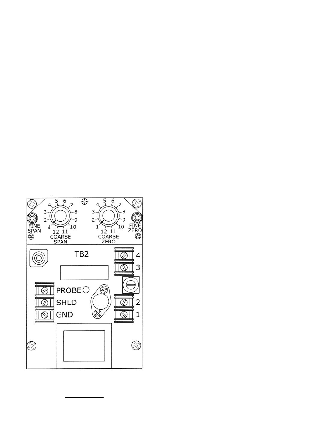
a) On units not containing an indicator, connect
an accurate milliammeter in series with the
output terminals 3(-) and 4(+).
b) Adjust the Coarse Span switch to position
No. 10.
c) With the process level in the vessel or tank
at the desired 0% (low) level, adjust the
Coarse and Fine Zero until the output current
indicates 0% (1, 0, 4 or 10 mA depending on
the output signal range of the Model 158A
Level-Tel being used). Clockwise rotation of
the zero adjustments will increase the output
current.
d) Change the process level in the tank to the
desired 100% (high) level and adjust the
Coarse and Fine Span until the output or
meter indicates 100% (5, 10, 20 or 50 mA
depending on the output signal range of the
Model 158A Level-Tel being used).
Clockwise rotation of the span adjustments
will increase the output current.
e) The instrument is now calibrated and ready
for operation. However, it is recommended
that the zero and span calibration be
repeated to obtain optimum accuracy.
4.3.2 Null Adjustment Calibration
THIS ADJUSTMENT IS FACTORY SET AND
SHOULD NOT BE REQUIRED. However, should
calibration of the null adjustment be required,
perform the following procedure:
a) With the Model 158A Level-Tel mounted and
the electrical connections made, adjust the
Coarse Span switch to position 10.
b) With the process level in the vessel or tank at
the desired 0% (low) level, adjust the Coarse
and Fine Zero adjustments until the output
current indicates 0% (1, 0, 4 or 10 mA
depending on the output of the Model 158A
Level-Tel being used). Clockwise rotation
increases the output current.
c) Adjust the Coarse Span switch to the No. 1
position.
d) Adjust the Null adjustment until the output
current or meter indicates 0%. Clockwise
rotation increases the output current.
e) Repeat steps “a” through “d” until the output
current remains at 0% when the Coarse
Span switch is rotated from position No. 1 to
position No. 10.
FIGURE 10
CALIBRATION ADJUSTMENTS
