4 Getting Started User Guide
I
NTRODUCTION
The Netopia™ Router is designed to be easy to connect, configure, and use. Netopia and your ISP together make it even easier for you to get your
router set up and connected to the Internet in a few minutes.
Once you’ve connected your router to your computer and to your telecommunications line and installed a web browser, you’re ready to run the
Netopia SmartStart Wizard.
Advanced users can find detailed documentation of advanced configuration options on the Netopia CD in the documentation folio accompanying your
Netopia Router.
C
ONTENTS
This booklet covers the following topics:
Ⅲ
“Making the Physical Connections” on page 4
Ⅲ
“Netopia Router Back Panel Ports” on page 4
Ⅲ
“Connecting to your Network” on page 5
Ⅲ
“Before running SmartStart” on page 5
Ⅲ
“Setting up your Router with the SmartStart Wizard” on page 6
Ⅲ
“Sharing the Connection” on page 10
M
AKING
THE
P
HYSICAL
C
ONNECTIONS
Identify the connectors and switches on the back panel and attach the necessary Netopia Router cables.
N
ETOPIA
R
OUTER
B
ACK
P
ANEL
P
ORTS
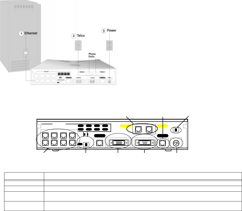
The figure below displays the back of the Netopia Router.
Netopia Router back panel
The following table describes all the Netopia Router back panel ports.
Port Description
Power port A mini-DIN8 power adapter cable connection.
Line port An RJ-45 jack labelled “Telco1” for your WAN connection. (The “Telco 2” port is reserved for future use.)
Console port A DE-9 console port for a direct serial connection to the console screens. You can use this if you are an experi-
enced user. See the on-line
User’s Reference Guide
on your Netopia CD.
Auxiliary port An HD-15 auxiliary port for attaching an external modem or the optional AppleTalk kit or the optional Analog Dial-in
kit (for RAS).
8
4
7
3
6
2
5
1
Telco 2 Telco 1
Phone 1Phone 2
1
8 port Ethernet hub Crossover switch
Line port
Auxiliary port Console port Power port
Termination switchPOTS ports (optional)
Ethernet
PowerConsole
Auxiliary
Normal/Uplink
1. Connect one of the RJ-45 cables to any of the Ethernet
ports on the router.
(If you are connecting the router to an existing Ethernet
hub, use Ethernet port #1 on the router and set the
crossover switch to the
Uplink
position.)
2. Connect one end of one of the RJ-45 cables to the “Telco
1" port, and the other end to your ISDN line outlet. (The
“Telco 2” port is reserved for future use.)
3. Connect the mini-DIN8 connector from the Power Adapter
to the Power port, and plug the other end into an electrical
outlet.
You should now have: the power adapter plugged in; the
Ethernet cable connected between the router and your
computer; and the telephone cables connected between
the router and the ISDN line jack.


