1PS2 mouse port 9Bit 2 (POST LED)
2System status LED 10LSB (POST LED)
3MSB (POST LED) 11Video port
4Bit 1 (POST LED) 12USB port 2
5Serial port 13USB port 3
6NIC port 1 (1 Gb) 14USB port 1
7NIC port 2 (1 Gb) 15USB port 0
8PS2 keyboard
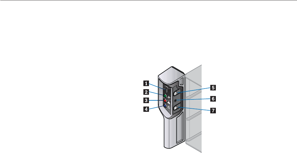
Connectors
The following connectors are located on the server board I/O panel:
v PS2 mouse port
v PS2 keyboard port
v Serial port
v Video port
v Two RJ-45 ports - NICs 1 and 2 (1Gb each)
v Four USB ports: 0, 1, 2, and 3
Server board LEDs
Status LEDs: Diagnostic LEDs are located on the server board I/O panel to assist
in identifying failed and failing components. See “Server board LEDs” on page 25
for a summary of status LED states.
NIC LEDs: The NIC LEDs at the right and left of each NIC port provide
information on NIC status. See “I/O panel NIC LEDs” on page 25 for a summary
of NIC LED states.
Front operator's panel
A front operator’s panel, consisting of a USB port, three LEDs and three
push-button switches, are located on the front of the enclosure.
Note:
The front operator’s panel is an integral part of the enclosure assembly and
is not field replaceable.
1USB port 5Power active LED
2Unit fault LED 6ID LED
Figure 8. Front operator’s panel components
Chapter 2. Features 7


