15
3
OPERATION
t Push [DOWN] to turn the position memory function
for the [INPUT] select switch ON.
• The band indicators, [1.8]–[50], light continuously.
y Rotate the 1st exciter’s dial until the LED [INPUT
z] lights continuously.
u Turn the 2nd exciter’s power ON.
i Push [INPUT].
• LED [INPUT x] blinks.
o Rotate the 2nd exciter’s dial until the LED [INPUT
x] lights continuously.
!0 Turn both exciter’s power OFF to complete the
setting.
ïï
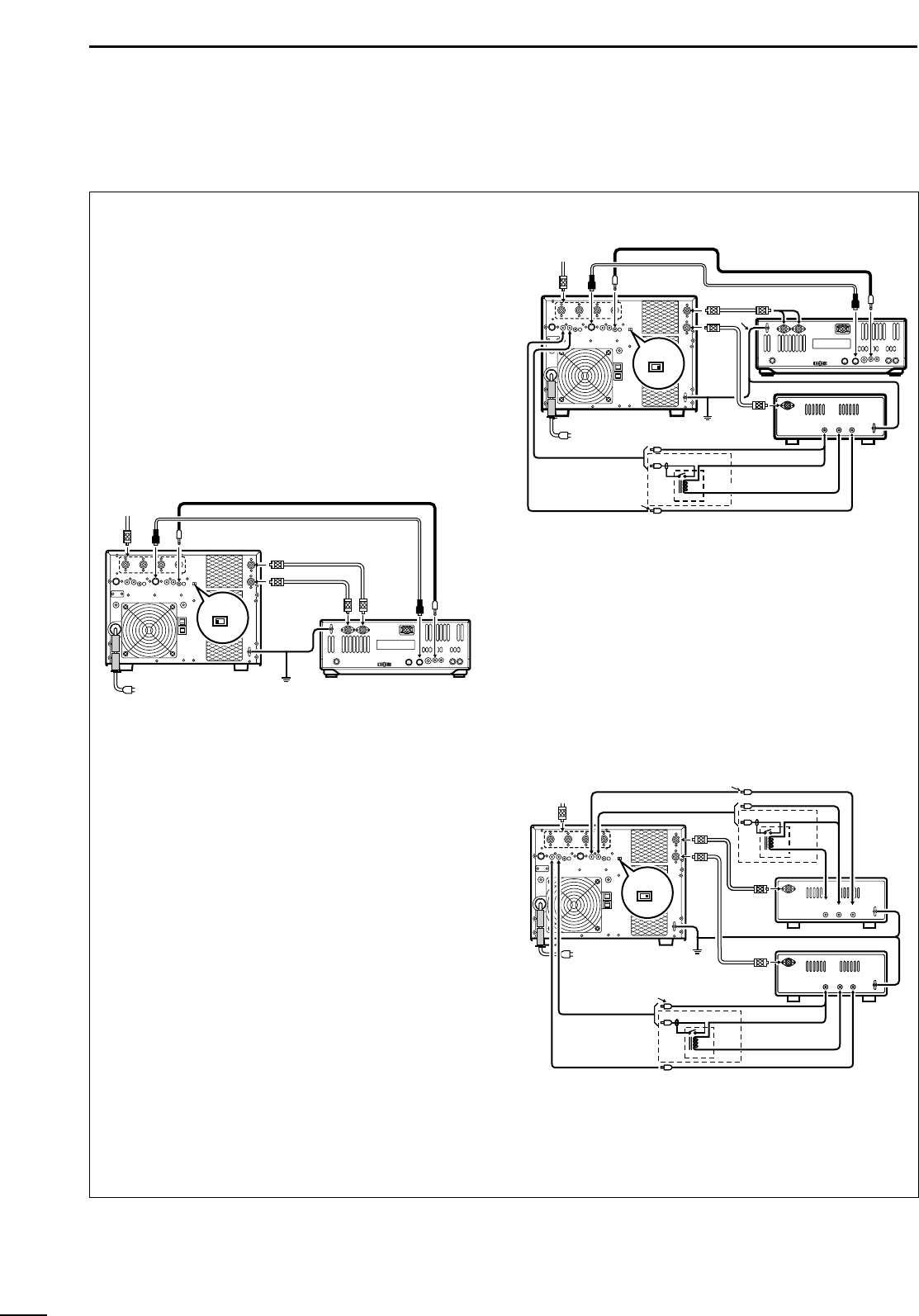
When using one (1) Icom exciter with two (2)
ANT lines (e.g. IC-756PRO etc.);
q Turn OFF both the IC-PW1/EURO and exciter.
w Set [EXCITER] to [1] position.
e While pushing and holding the [INPUT] switch on
the IC-PW1/EURO controller, turn the exciter’s
power ON.
• LED [INPUT z] blinks.
r Rotate the exciter’s dial until the LED [INPUT z]
lights continuously.
t Push [INPUT].
• LED [INPUT x] blinks.
y Rotate the exciter’s dial until the LED [INPUT x]
lights continuously.
• The band indicators, [1.8]–[50], turn OFF.
•“AUTO” indicator lights continuously.
u Turn the exciter’s power OFF to complete the set-
ting.
ïï
When using one (1) Icom and one (1) non-
Icom exciter;
q Turn OFF both the IC-PW1/EURO and exciters.
w Set [EXCITER] to [1&2] position.
e While pushing and holding the [INPUT] switch on
the IC-PW1/EURO controller, turn the 1st exciter’s
power ON.
• LED [INPUT z] over the [INPUT] switch blinks.
r Rotate the exciter’s dial until the LED [INPUT z]
lights continuously.
t Turn the exciter’s power OFF to complete the set-
ting.
ïï
When using two (2) non-Icom exciters;
➥ Set [EXCITER] to [1&2] position, only.
*No other setting is required.