February 1994 Hewlett-Packard Journal 77
Reducing Stepper Noise. Once we had the speed that we
needed, we had several more hurdles to pass. It was neces-
sary to control the motor and make it start and stop pre-
cisely without the noises that normally come from stepper
motors. When the first DeskJet 1200C lab prototypes were
built, people were very concerned about the stepper noise.
Hardware was developed that allows the dynamic response
of both the motor and the gear-driven shaft to be measured.
This hardware was combined with personal-computer-based
software that makes the process of smoothing out the step
profile of the motor relatively easy. Because the designers
had been clever enough to make it easy to download step
times to the printer, it was possible to try out different com-
binations of step times quickly and observe the response of
the motor and drive shaft visually (in addition to hearing it).
The dynamic response was successfully smoothed out and
the system became much quieter. At the same time, we were
also anticipating problems with overshoot.
Controlling Backlash. Fig. 6 shows the function of the anti-
backlash device. The purpose of this sheet-metal spring is to
keep the teeth of the gears meshed tightly even if the motor
backs up slightly. If the gears were to become unmeshed,
the resultant accuracy error would be twice as much as all
other error sources combined.
The DeskJet 1200C media axis completes a 1/3-inch swath
advance in under 58 milliseconds. (For comparison, the
PaintJet XL300 completes a 1/6-inch swath advance in about
200 milliseconds.) Hence, it was expected that it would be
difficult or impossible to prevent gear backlash. However,
we came up with a way to reduce this backlash. The idea is
to use a piece of sheet-metal steel that pinches the gears,
adding friction so that when the motor stops and backs up,
the gears follow it backwards. This steel antibacklash device
has three springs built into one component. The first spring
applies a controlled pinch force on the gear. The second
spring is stretched forward every time the motor moves for-
ward and provides the restoring force or antibacklash func-
tion. The third spring provides a thrust load that keeps the
plastic gears pushed against the motor mounting plate.
Motor Pinions. One of the most difficult challenges on the HP
DeskJet 1200C printer was to achieve an overall accuracy
goal that was as good as the PaintJet XL300 over twice the
distance of that printer. It turns out that one of the key com-
ponents in the DeskJet 1200C mechanism is the quality of
the motor pinions. We chose to hob the pinions instead of
molding them because their relatively small size makes hob-
bing relatively low in cost. Also, hobbing is substantially
more accurate. Gear accuracy is commonly measured in the
industry, and the key measurement is called total composite
error or TCE. This measurement is very similar to runout
and essentially behaves the same way as runout. However,
while it is easy to measure runout on a motor-driven smooth
shaft, it is difficult to measure the TCE of a pinion after it
has been mounted on the motor shaft, especially with a step-
per motor. To measure the TCE of a pinion after it has been
mounted on the motor shaft, it is necessary to turn the motor
very smoothly and slowly at only a few r/min. So, first we
designed the stepper motor (which is by nature very oscilla-
tory) to go extremely fast, and then we tried to drive it at
very slow speeds. We were only able to make the motor
move at slow speeds by using two function generators con-
strained in a phase-locked loop to be 90 degrees out of phase,
then connecting their amplified outputs to the phases of the
motor. Effectively, this became a sine-wave drive for the
stepper, and it did successfully drive the permanent magnet
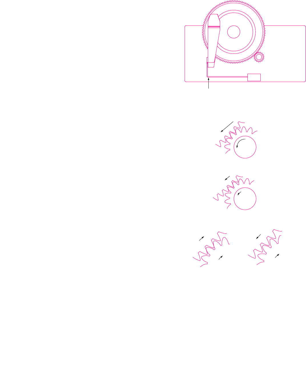
Fig. 6. Controlling the backlash. The large drawing at the top shows
the function of the antibacklash device. The purpose of the backlash
sheet-metal spring is to keep the teeth of the gears meshed tightly
even if the motor backs up slightly. If the gears were to become un-
meshed, the resultant accuracy error would be twice as much as all
other error sources combined. The middle drawings show the motor
moving forward and the motor slowing down but still moving for-
ward. The two drawings on the bottom show the backlash spring
working (left) and the backlash spring not working (right).
The Function of the Anti-Backlash Spring
Motor Moves Forward
Motor Slows Down, but
Still Moving Forward
Anti-Backlash
Spring Working
Anti-Backlash Spring
Not Working
Motor backs up slightly and stops.
Teeth stay tightly meshed because the
backlash device pulls the big gear
backwards against the small gear.
Motor backs up slightly and stops. Teeth
have become unmeshed because the big
gear continued to move forward while the
motor was backing up. This is a failure.
Anti-Backlash Spring


