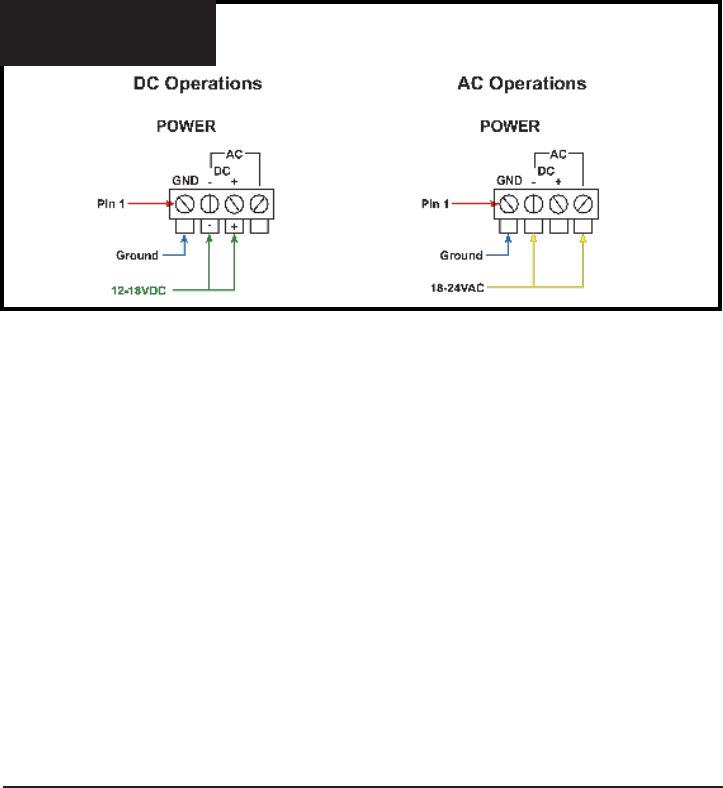
Fig. 2
Power Wiring Diagram
P.O. Box 749 Peekskill, NY 10566 Tel: (845) 737-7009 Fax: (845) 737-0426 Web: www.compuvideosystems.com
Installation:
Mount CCA-200: Before the unit is to be mounted you will need determine where to mount
it, allowing for clearance for the BNC connectors and the cables. Do not mount the unit
over a heat source! Using the four #8 screws, secure the unit to the mounting surface.
The CCA-200 can be mounted in an equipment rack if there are rear rails. The cover
mounting holes will match up on one side with the EIA rack rails. Use whichever screws the
rack setup needs to mount the CCA-200.
After the CCA-200 has been mounted, connect the power.
On the CVT-1230 power pack, the wire with the white trace is the Positive (+) and the
unmarked wire is the Negative(-) lead. If you reverse these, the unit will not operate.
Simply reverse the leads to make the unit function.
Using Figure 2, connect the CVT-1230 to the CCA-200. Once power connections are
made, pin 1 and 4 should be open. Pin 1 will be used if a ground is tied to the unit.
If you are to use a 24VAC camera power pack use Figure 3 for the connections. Once
connected pin 1 and 3 should remain open unless a ground is tied to pin 1.
Make sure that the wires are secure in the power connector. It is recommended that
an earth ground is connected to the unit. This cannot be the same as the (-) on the
12-18VDC or one side of the AC power.


