• The edge of the squareand the saw bladeshould
be parallelas shownin figure 17.
• Ifthe front orbackedge of the saw bladeangles
away from the squareas showninfigures 18 and
19, adjustmentsare needed.
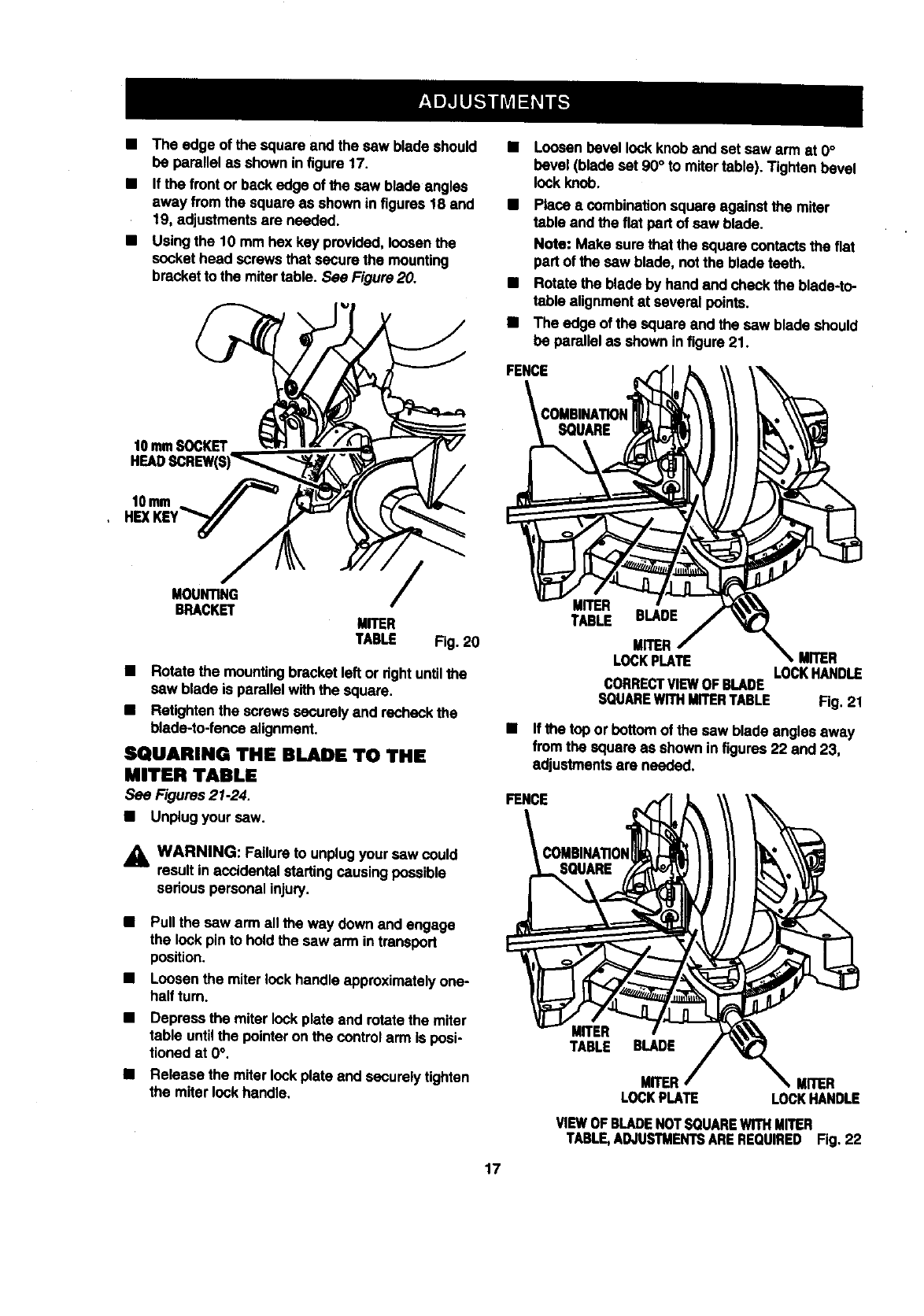
• Usingthe 10 mm hex key provided,loosenthe
sockethead screwsthat secure the mounting
brackettothe mitertable. See Figure20.
Loosenbevel lockknoband set saw arm at 0°
bevel (bladeset 90° to mitertable). Tightenbevel
lockknob.
Place a combinationsquareagainst the miter
table and the flat part ofsaw blade.
Note= Make sure that the squarecontactsthefiat
partofthe saw blade, notthe bladeteeth.
• Rotate the blade byhand and checkthe blade-to-
table alignmentat several points.
• The edge ofthe square and the saw bladeshould
be pe.mllal as showninfigure 21.
FENCE
f0 mmSOCKET
10mln ._
HEXKEY"_"
M_NTING
B_CK_
/
MITER
TABLE
Fig. 20
• Rotate the mountingbracketleft or right untilthe
saw blade is parallelwiththe square.
• Retightenthe screwssecurelyand recheckthe
blade-to-fansaalignment.
SQUARING THE BLADE TO THE
MITER TABLE
See Figures21.24.
• Unplugyoursaw.
,_k WARNING: Failureto unplugyoursaw could
resultin accidentalstaffingcausingpossible
serious personalInjury.
Pullthe saw arm all the way downand engage
the lockpinto holdthe saw arm intransport
position.
Loosenthe miter lockhandle approximatelyone-
halfturn.
Depress the miterlock plate and rotatethe miter
table untilthe pointeron the controlarm Is posi-
tioned at 0°.
Release the miterlockplate end securelytighten
the miterlockhandle.
MITER
TABLE BLADE
MITER
LOCKPLATE MITER
LOCKHANDLE
CORRECTVIEWOFBLADE
SQUAREWITHMITERTABLE Fig. 21
• Ifthe top or bottomofthe saw bladeanglesaway
fromthe squareas shownin figures22 and 23,
adjustmentsare needed.
FENCE
MITER
TABLE BLADE
MITER MITER
LOCKPLATE LOCKHANDLE
VIEWOFBLADENOTSQUAREWITHMITER
TABLE,ADJUSTMENTSAREREQUIRED Fig, 22
17


