4-3
Network diagram
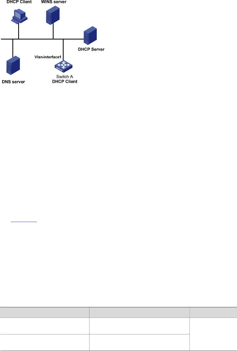
Figure 4-1 A DHCP network
Configuration procedure
The following describes only the configuration on Switch A serving as a DHCP client.
# Configure VLAN-interface 1 to dynamically obtain an IP address by using DHCP.
<SwitchA> system-view
[SwitchA] interface Vlan-interface 1
[SwitchA-Vlan-interface1] ip address dhcp-alloc
BOOTP Client Configuration Example
Network requirement
Switch B’s port belonging to VLAN1 is connected to the LAN. VLAN-interface 1 obtains an IP address
from the DHCP server by using BOOTP.
Network diagram
See Figure 4-1.
Configuration procedure
The following describes only the configuration on Switch A serving as a client.
# Configure VLAN-interface 1 to dynamically obtain an IP address from the DHCP server.
<SwitchA> system-view
[SwitchA] interface vlan-interface 1
[SwitchA-Vlan-interface1] ip address bootp-alloc
Displaying DHCP/BOOTP Client Configuration
To do… Use the command… Remarks
Display related information on a
DHCP client
display dhcp client [ verbose ]
Display related information on a
BOOTP client
display bootp client [ interface
Vlan-interface vlan-id ]
Optional
Available in any
view


