


5
ASSEMBLY
Assembly requires two people. Set the treadmill in a cleared area and remove all packing materials. Do not
dispose of the packing materials until assembly is completed. Refer to the drawings below to identify the small
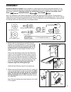
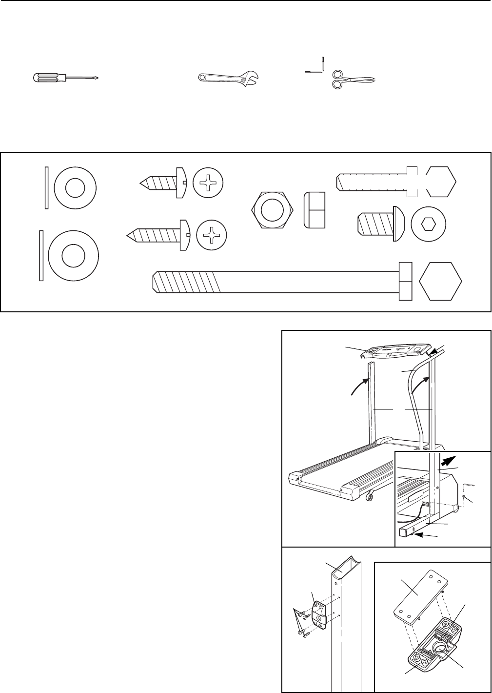
parts used in assembly. Assembly requires the included allen wrench and your own phillips screw-
driver , adjustable wrench , and scissors .
Note: The underside of the treadmill walking belt is coated with high-performance lubricant. During shipping, a
small amount of lubricant may be transferred to the top of the walking belt or the shipping carton. This is a normal
condition and does not affect treadmill performance. If there is lubricant on top of the walking belt, simply wipe off
the lubricant with a soft cloth and a mild, non-abrasive cleaner.
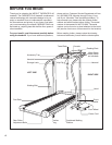
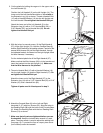
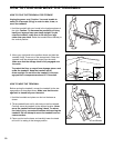
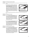
1. With the help of a second person, carefully raise the
Uprights (14), the Right Handrail (57), and the Console
Base (6) until the treadmill is in the position shown. Be
careful not to pull on the Wire Harness (26). Set the
Right Handrail on the right Upright until step 3 is com-
pleted.
Refer to the inset drawing. Insert one of the Extension
Legs (41) into the treadmill as shown. (Note: It may be
helpful to tip the Uprights (14) in the direction shown by
the arrow as you insert the Extension Leg.) Make sure
that the Base Pad (36) is on the bottom of the Extension
Leg. Attach the Extension Leg with an Extension Leg
Screw (34). Be sure to push on the head of the
Extension Leg Screw while tightening it.
Attach the other Extension Leg (41) in the same way.
1
1/4Ó Washer (16)Ð2
Extension Leg Screw (34)Ð2
3 1/2" Handrail Bolt (59)Ð2
5/16" Washer (32)Ð2
Handrail Bolt (15)Ð2
Screw (55)Ð8
Handrail Nut (82)Ð2
Reading Rack Screw (74)Ð4
34
41
14
26
14
57
6
36
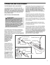
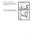
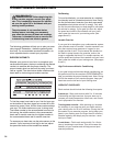
2. Without removing the tape from the Latch (12), attach the
Latch to the left Upright (14) with four Screws (55). Make
sure that the Screws are tight, but do not overtighten
them; if the Screws are overtightened, the Latch will
not slide smoothly. After the Latch is attached, remove
any visible tape.
Note: The inset drawing shows how the parts of the Latch
(12) fit together.
12
55
14
2
Spacer
Springs
Bracket
Latch