


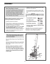
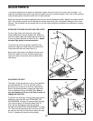
This section explains how to adjust the resistance system. See the EXERCISE GUIDELINES on page 17 for
important information about how to get the most benefit from your exercise program. Also, refer to the accompa-
nying exercise guide to see the correct form for each exercise.
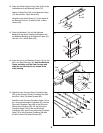
Make sure all parts are properly tightened each time you use the resistance system. Replace worn parts immedi-
ately. The resistance system can be cleaned with a damp cloth and a mild, non-abrasive detergent. Do not use
solvents. The crossbows can be cleaned with a vinyl and rubber protectant, available at an automotive or depart-
ment store.
13
Ball
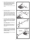
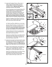
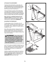
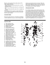
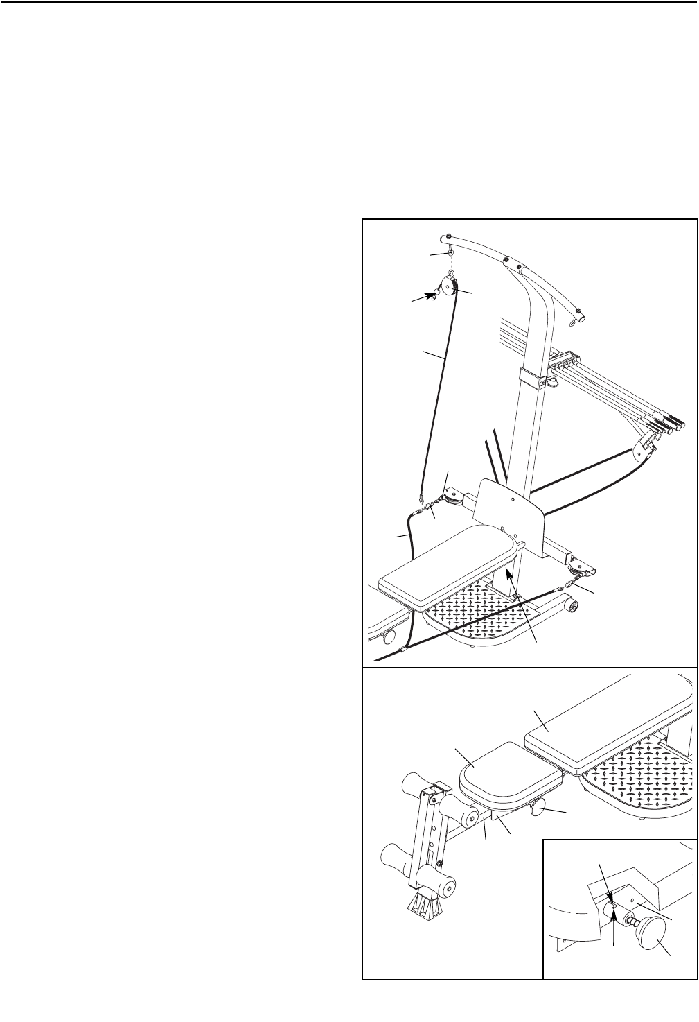
ATTACHING THE HIGH PULLEYS AND LEG LEVER
To use a high pulley, slide the hook on the High
Pulley Housing (21) onto the Eyebolt (34). Attach the
end of the Short Cable (33) without the ball to the end
of the Long Cable (80) with a Cable Clip (51). Attach
the other high pulley in the same manner.
To use the Leg Lever (not shown), attach the two
ends of the Leg Lever Cable (32) to the ends of the
Long Cable (80) with two Cable Clips (51).
Remove the high pulleys, and detach the Leg Lever
Cable (32), when not in use. Store the ends of the
Leg Lever Cable on the hook under the Bench Rail
(not shown).
33
21
51
51
Hook
80
32
34
ADJUSTMENTS
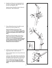
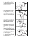
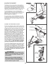
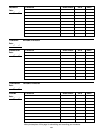
ADJUSTING THE SEAT
The Seat (13) can be secured in any of four positions
on the Bench Rail (5). To move the Seat, pull the
Seat Knob (45) out as far as it will go, and slide the
Seat to the desired position. Engage the Seat Knob
into an adjustment hole in the Bench Rail. Note: It
may be necessary to lift up on the Seat in order to
engage the Seat Knob.
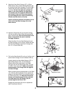
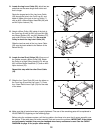
To perform row exercises, the leg press strap must be
attached to the long cable (see ATTACHING THE
ACCESSORIES, on page 14), and the Seat Carriage
(12) must be able to roll along the Bench Rail (5).
First, remove the Backrest (14) from the Seat
Carriage (see ADJUSTING THE BACKREST on page
15). Then, pull the Seat Knob (45) out as far as it will
go, and turn the Knob so that the pin rests at the end
of the “L”-shaped slot (see the inset drawing).
13
14
45
12
5
12
45
Pin
“L”-Slot