4
ASSEMBLY
1
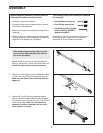
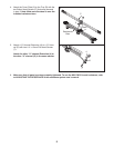
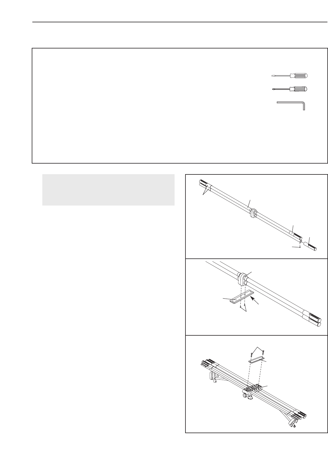
1.
Attach a Cap (2) to one end of the Resistance
Bars (1) with an M4 x 12mm Flat Head Screw (5).
Attach the other Caps in the same manner.
2. Attach the Cover Plate (3) to the Resistance Bars
(1) with two 1/4" x 25mm Flat Head Screws (6).
Make sure the Cover Plate is oriented with the
edges up.
3.
Locate the
T
ray (B) on the resistance system.
Remove the two indicated Button Head Screws
(C) and the Cover Plate (A) from the Tray. Set the
Cover Plate aside.
Note: The resistance bar
assembly is shown removed from the resis-
tance system for clarity.
Before beginning assembly, make sure that
you have read and understand the informa-
tion in the box above.
1
5
3
Edges
Up
3
2
2
2
2
1
C
B
6
A
Before beginning assembly, carefully read the
f
ollowing information and instructions:
• Assembly requires two people.
• Tighten all parts as you assemble them, unless
instructed to do otherwise.
• Make sure all parts are oriented as shown in the
drawings.
• Place all parts in a cleared area and remove the
packing materials. Do not dispose of the packing
materials until assembly is completed.
The following tools (not included) are required
f
or assembly:
• One standard screwdriver
• One Phillips screwdriver
• One Allen wrench (included
with the MAX by WEIDER
resistance system)
Assembly will be more convenient if you have a
socket set, a set of open-end or closed-end
wrenches, or a set of ratchet wrenches.


