


7
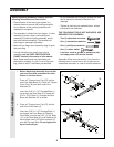
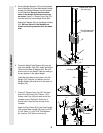
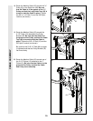
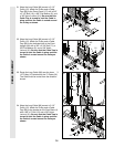
8. Attach the upper ends of the Weight Guides
(62) to the Top Frame (55) with the 5/16” x 6”
Bolt (60), two 1/2” x 3/4” Spacers (61), and a
5/16” Nylon Locknut (3).
Tighten all Nylon Locknuts used in steps 2
through 8.
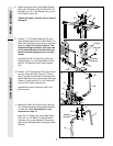
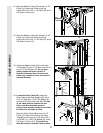
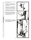
9. Press a 1” x 7/8” Plastic Bushing (75) onto
each welded spacer on the Press Frame (17).
Slide the Press Frame into place on the Front
Base (4). Note: This will be a tight fit. The
Plastic Bushings should fit onto each end
of the indicated tube in the Base. Be sure
that the indicated pulleys are on the side
shown.
Lubricate the 3/8” x 8” Bolt (59). Attach the
Press Frame (17) to the Front Base (4) with
the 3/8” x 8” Bolt and a 3/8” Nylon Locknut
(21).
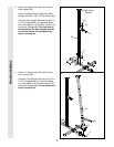
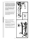
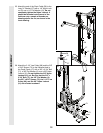
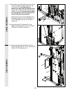
10. Press a 1 3/4” Square Inner Cap (44) into the
top of a Press Arm (46). Press a 1” Round
Inner Cap (49) into the side of the Press Arm.
Attach the Press Arm to one side of the Press
Frame (17) with two 5/16” x 2 1/2” Bolts (22)
and two 5/16” Nylon Locknuts (3).
Assemble the other Press Arm (46) in the
same manner.
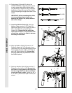
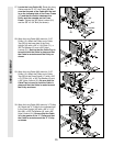
11. Identify the Right Arm (48) and the Left Arm
(47). Note the position of the welded bracket
on each Arm. Arm identification is very
important for step 12.
Note: The “V”-Pulleys (6), Long Cable Traps
(50), 3/8” x 2 1/2” Bolts (7), and 3/8” Nylon
Locknuts (21) are pre-attached. These have
been shown disassembled for easy part iden-
tification.
8
10
11
ARM ASSEMBLY FRAME ASSEMBLY
62
61
3
60
55
17
4
Tube
75
Welded
Spacers
Pulleys
21
44
44
49
46
46
22
3
50
Welded
Brackets
21
48
47
9
Lubricate
59
17
49
7
6
50