


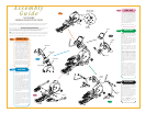

3
STEP
• Slide one wave washer (26x35x0.3T),
one flat washer (25.5x38x1T), and
one wave washer (25.5x34x2T) onto
the axle of the right link arm. Slide the
axle of the right link arm through the
sleeve on the right pedal arm. Secure
the link arm onto the pedal arm with
the wave washer (25.5x34x2T), end
cap, and bolt (M8x12L). Tighten with
the 5mm L-shaped wrench.
• Repeat the step on the left side.
PINK BAG
4
STEP
NOTE:
With this next step it is helpful
to have a second person to hold the
dual-action arms in place while you
assemble them.
• Take the right dual-action arm and
center the holes in the rotation housing
on the console mast. Secure with four
socket head bolts (M8x25L) and four
lock washers (M8). Tighten with the
6mm T-shaped wrench.
• Attach the dual-action arm rotation
cover to the dual-action arm center.
Secure in place with two bolts
(M5x15L). Tighten with the screwdriver.
• Slide a spacer onto each side of the
socket joint located on the end of the
link arm. Slide the bottom of the dual-
action arm bracket over the link arm
socket and spacers. From the outside
of the bracket, slide the bolt (M8x55L)
through the hole in the bracket and
socket joint. Secure with a washer
(8x16x1T) and nut (M8). Tighten with
the 6mm T-shaped wrench and 13mm
wrench.
• Attach the inside dual-action arm
cover onto the bottom of the dual-
action arm with a bolt (M5x15L).
Insert the plastic connector to the
inside dual-action arm cover. Slide the
outside dual-action arm cover onto the
other end of the plastic connector.
Secure the outside dual-action arm
cover to the bottom of the dual-action
arm with a bolt (M5x15L). Tighten
both bolts with the screwdriver.
• Repeat these steps on the left side.
GREEN BAG
Assembly
Guide
X6750HRT
COMMERCIAL INCLINE ELLIPTICAL TRAINER
2
STEP
5
STEP
• Slide the accessory tray onto the
console mast. Secure in place with
four bolts (M8x20L). Tighten with the
5mm L-shaped wrench.
• Remove the four bolts (M5x12L)
from the back side of the console.
Connect the wire harness and the
heart rate wires to the plugs in the
back side of the console. Place the
console on the mast and secure in
place with the bolts (M5x12L).
• Place the X6750HRT in its intended
location and plug in the power cord
to the electrical outlet.
BLACK BAG
3
STEP
To avoid possible damage to this Elliptical Trainer, please follow these assembly steps in the correct order. Before
proceeding, find your new Elliptical Trainer’s serial number located on the front axle tube, and enter here:
Refer to this number when calling for service, and enter this serial number on your Warranty Card and in
your own records. Be sure to read your Owner’s Guide before using your new Elliptical Trainer.
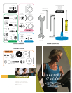
If any parts, hardware or tools are missing, please call 1.800.335.4348, Extension 12
NOTE: It is recommended that you apply grease to the threads of each bolt and screw as you assemble your
Elliptical Trainer to prevent loosening and noise. Also, during each assembly step, ensure that ALL bolts and
screws are in place and partially threaded in before completely tightening any ONE bolt or screw.
5
STEP
4
STEP
Console Mast
Boot
Mounting Plate
Console Mast
Frame Bracket
Link Arm
Pedal Arm
Rotation
Housing
Dual-Action
Arm
Console
Accessory Tray
2
STEP
• Slide the console mast boot onto the
console mast.
• Attach the mounting plate to the
bottom of the console mast with four
socket head bolts (M8x15L) and four
lock washers (M8). Tighten with the
6mm L-shaped wrench.
• Mount the console mast on the
frame by sliding the guide hole on the
mast mounting plate over the guide
screw on the front of the frame bracket.
Place a lock washer (M8) followed by
a flat washer (8x16x2T) on each of
the four remaining socket head bolts
(M8x15L) and use them to fix the mast
to the frame. Tighten with the 6mm
L-shaped wrench.
• Wrap the wire tie that exits the hole
at the bottom front side of the console
mast around the wire harness coming
up from the frame. Pull the wire tie
and wire harness up through the top
of the console mast.
• Insert a zip tie through the hole in
the middle of the console mast and
loop it around the heart rate wires and
wire harness. Pull to snug, but do not
over tighten.
BLUE BAG
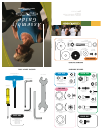
1
STEP
Teflon side should
face other washer
Teflon Side
(top)
Teflon Side
(bottom)
1
STEP
• Take the right pedal arm and set the
roller wheel in the aluminum rail track.
On the connection end of the pedal
arm place a teflon washer (10x38x1T)
on each side of the connection
sleeve. The teflon side should face
away from the sleeve. Now place a
regular flat washer (10x38x1T) against
the teflon washer. Slide the end of the
pedal arm with washers into the
knuckle pin bracket. Slide a socket
head bolt (M10x55L) with washer
(10x24.5x1T) through the hole in the
knuckle pin bracket and pedal arm.
Fix in place with a washer (10x24.5x1T)
and nut (M10). Tighten with the 8mm
L-shaped wrench and the 17mm wrench.
• Slide the pedal arm cover over the
knuckle joint and fix in place with a bolt
(M5x12L). Tighten with the screwdriver.
• Repeat these steps on the left side.
ORANGE BAG