


4
STEP
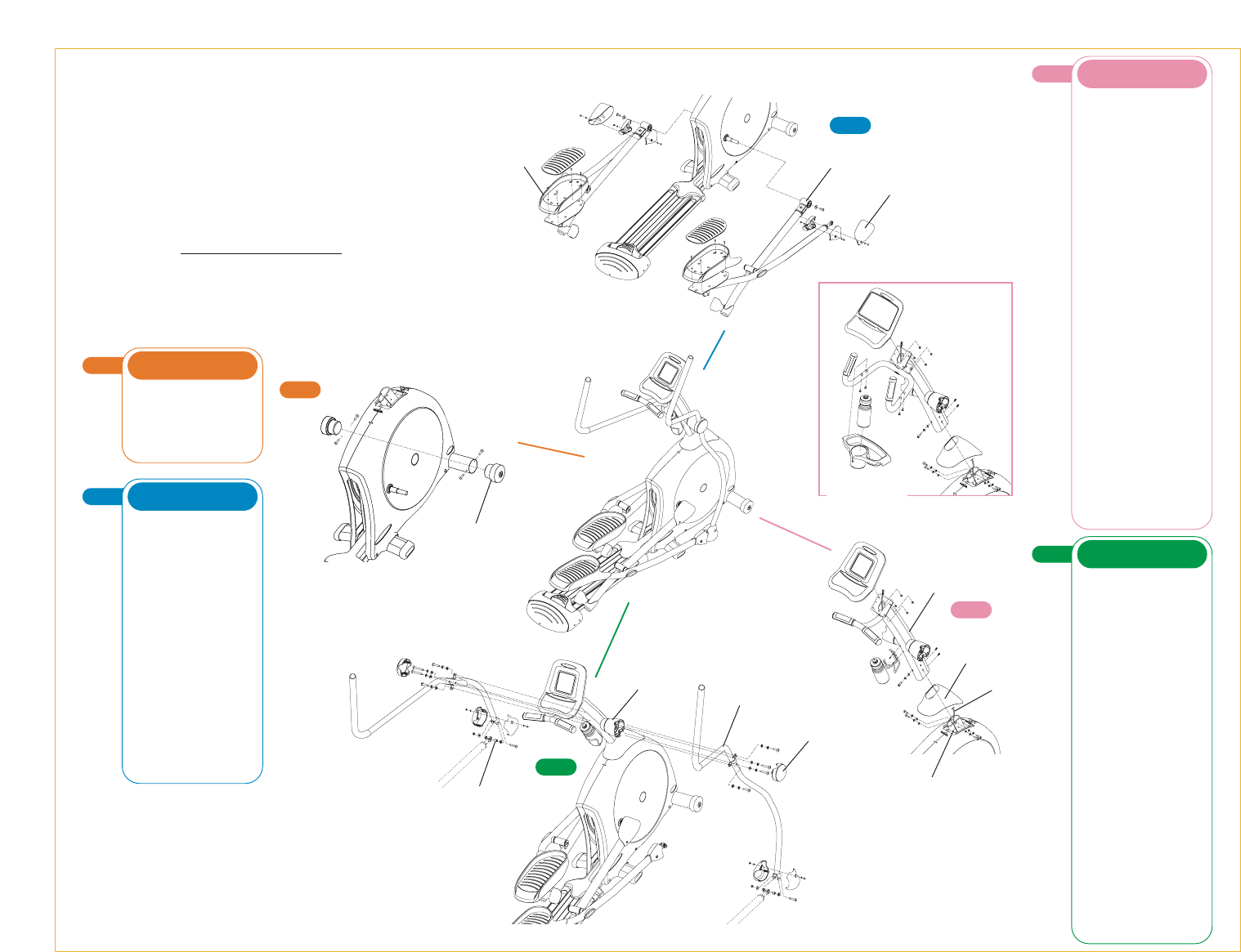
• Line up the holes in the right dual-
action arm with the holes on the right
rotation housing. Insert two bolts
(M8x60L), with a lock washer (M8)
and an arc washer (8x18x1.5T),
through the holes in the center of the
dual-action arm and thread into the
rotation housing. Next, insert two fully
threaded bolts (M8x45L), with a lock
washer (M8) and a flat washer
(8x18x1.5T), through the flange on
the side of the dual-action arm and
into the rotation housing. Tighten all
bolts with the 5mm T-handle wrench.
• Position the rotation housing cap over
the dual-action arm and snap in place.
• Slide the axle sleeve through the
socket joint on the right link arm. Slide
a spacer ring onto each side of the
axle sleeve.
• Slide the link arm axle sleeve
between the teeth on the bottom of the
dual-action arm bracket. Insert a bolt
(M8x45L) through the dual-action arm
bracket and link arm axle sleeve. Fix
in place with a washer (8x25x1.5T)
and nut (M8). Tighten with the 13mm
wrench and 5mm L-shaped wrench.
• Attach a cover to the left and right
side of the dual-action arm connection
joint. Fix each side in place with the
washer (5x10x1T) and bolt (M5x10L).
Tighten with the screwdriver.
• Repeat these steps on the left side.
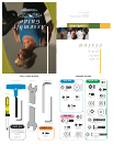
GREEN BAG
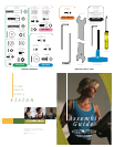
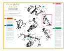
Assembly
Guide
X6150 AND X6250HRT
INCLINE ELLIPTICAL TRAINERS
To avoid possible damage to this Elliptical Trainer, please follow these assembly steps in the correct order. Before
proceeding, find your new Elliptical Trainer’s serial number located on the front axle tube, and enter here:
Refer to this number when calling for service, and enter this serial number on your Warranty Card and in
your own records. Be sure to read your Owner’s Guide before using your new Elliptical Trainer.
If any parts, hardware or tools are missing, please call 1.800.335.4348, Extension 12
NOTE: It is recommended that you apply grease to the threads of each bolt and screw as you assemble your
Elliptical Trainer to prevent loosening and noise. Also, during each assembly step, ensure that ALL bolts and
screws are in place and partially threaded in before completely tightening any ONE bolt or screw.
3
STEP
• Slide the console mast boot onto the
console mast.
• Unwrap the wire harness located in
the console mast frame bracket. Take
the wire tie that exits the bottom of the
console mast and wrap it around the
end of the wire harness. Pull the wire tie
up through the top of the console mast
and slide the bottom of the console mast
over the console mast frame bracket.
• Insert a socket head bolt (M8x25L)
with a lock washer (M8) and a flat
washer (8x18x1.5T) to each of the four
mounting holes on the sides of the
console mast. Insert a socket head bolt
(M8x25L) with a lock washer (M8) and
an arc washer (8x18x1.5T) to the
mounting hole on the backside of the
console mast. When all bolts are in
place tighten the bolts with the 6mm
L-shaped wrench. Insert two sets screws
(M8x10L) to the nuts welded in the front
side of console mast and tighten them
with a 4mm L -shaped wrench.
• Slide the console mast boot down
in place over the frame covers.
• Remove the four mounting screws from
the backside of the console. Plug the
wire harness and heart rate wires into
the back side of the console. Mount the
console to the console mast with the four
screws removed earlier in this step.
X6250 ONLY:
Set the accessory tray
on the console mast handlebars.
Secure in place with four screws
(M5x12L). Tighten with the screwdriver.
X6150 ONLY:
Remove the water
bottle cage mounting screws from the
console mast with the screwdriver.
Mount the bottle cage to the mast with
these same screws. Insert water bottle.
PINK BAG
1
STEP
• Slide the right transport wheel into the
front tube. Align the holes in the front
tube with the screw holes in the transport
wheel sleeve. Insert two screws
(M4x15L). Tighten with the screwdriver.
• Repeat these steps on the left side.
ORANGE BAG
2
STEP
• Slide the knuckle joint sleeve of the
right pedal arm assembly onto the pin
on the right side cover disk. Secure in
place with a washer (8x25x1.5T)
and bolt (M8x20L). Tighten with the
5mm T-handle wrench.
• Slide the knuckle joint cover over
the knuckle joint. Fix in place with a
washer (5x10x1T) and a bolt (M5x10L).
Tighten with the screwdriver.
• Attach a cover to the left and right
side of the link arm connection joint.
Fix each side in place with a washer
(5x10x1T) and a bolt (M5x10L).
Tighten with the screwdriver.
• Assemble the pedal footwell onto
the right pedal arm with four flathead
bolts (M5x12L). Tighten with the
screwdriver.
• Insert the footwell cushion into the
footwell. Make sure all pegs are seated
into their respective holes.
• Repeat these steps on the left side.
BLUE BAG
3
STEP
4
STEP
2
STEP
Knuckle Joint
Sleeve
Knuckle Joint
Cover
Pedal Footwell
Console Mast
Boot
Wire Harness
Console Mast
Console Mast
Frame Bracket
Dual-Action Arm
Rotation Housing
Rotation
Housing Cap
Link Arm
Axle Sleeve
1
STEP
X6250HRT ONLY
X6150
Transport
Wheel