


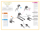
Assembly
Guide
To avoid possible damage to this Platform Treadmill, please follow these assembly steps in the correct
order. Before proceeding though, find your new Platform Treadmill’s 2 serial numbers, located on the
underside of the main frame, and on the bottom of the console, and enter here:
Refer to these numbers when calling for service, and also enter these serial numbers on your Warranty
Card and in your own records. Be sure to read your Owner’s Guide before using your new Platform Treadmill.
If any parts, hardware or tools are missing, please call 1.800.335.4348, Extension 12
NOTE: It is recommended that you apply grease to the threads of each bolt as you assemble your Platform
Treadmill, to prevent loosening and noise. Also, during each assembly step, ensure that ALL nuts and bolts
are in place and partially threaded in before completely tightening any ONE bolt.
1
STEP
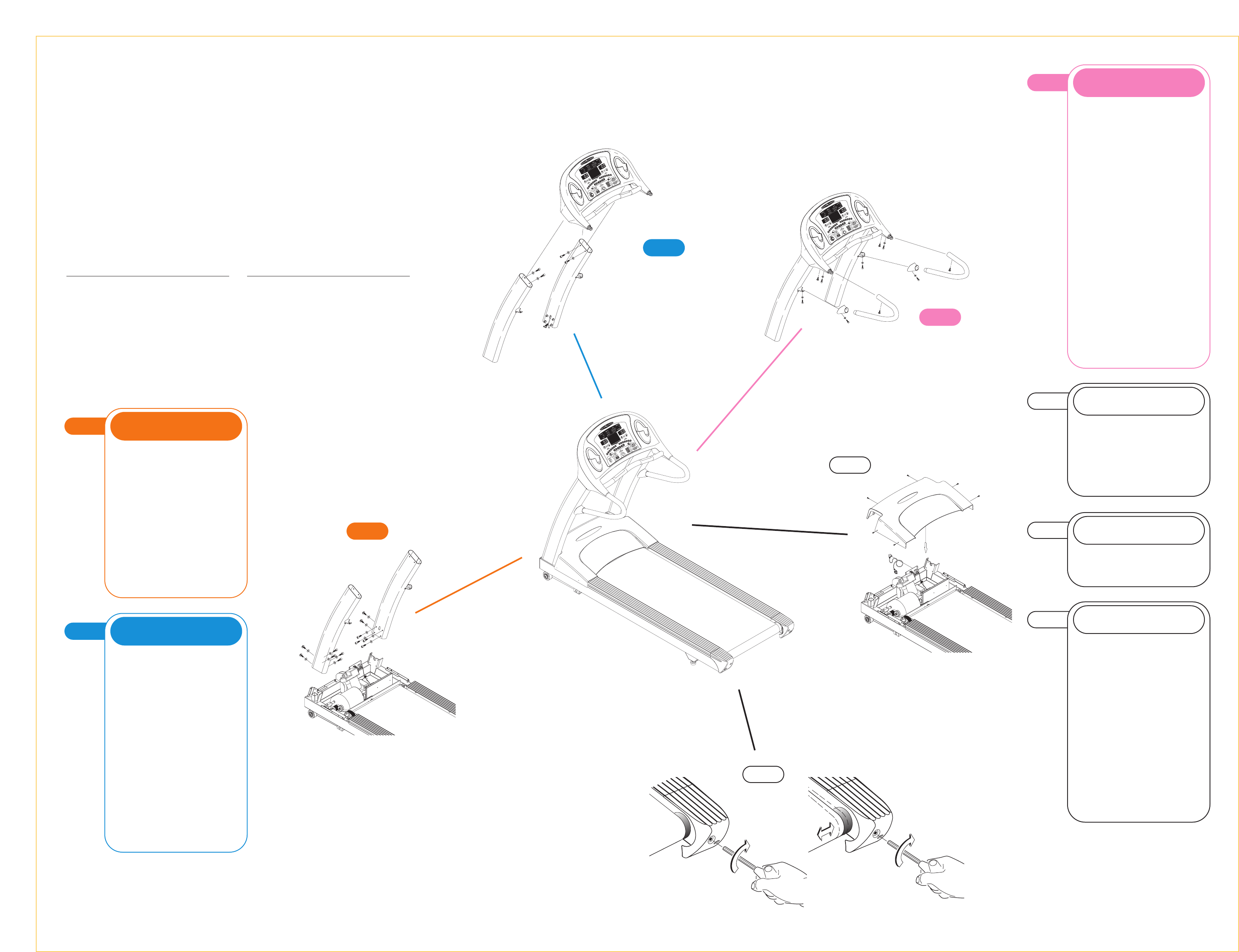
• Remove motor cover screws and
take off the motor cover.
• Insert the right console mast to the
right console mast bracket. First, fasten
the inside of the console mast to the
console mast bracket by securing four
bolts (M8x15L socket head) and four
washers (8.2x19x2T). Fully tighten the
bolts. Second, fasten the two bolts
(M10x15L button head) and two
washers (10.2x19x2T) on the front of
the console mast and fully tighten.
• Repeat on the left side
ORANGE BAG
1
STEP
2
STEP
3
STEP
• Insert the handlebar cover onto the
handlebar. Insert the right handlebar
by holding the handlebar sideways
toward the treadmill and inserting the
top into the console. Rotate the
handlebar into the bracket located on
the console mast. Fasten with a bolt
(M5x12L), and a bolt (M6x15L socket
head) & an arc washer (6x13x2T) into
the two holes of the console plastic,
and a bolt (M8x15L flat head) into the
hole in the handlebar. Fasten a bolt
(M6x15L socket head) and a flat wash-
er (6x20x2T) into the hole in the handle-
bar on the console mast. Do not fully
tighten the bolts.
• Slide the handlebar cover over the
bracket and secure with a bolt
(M6x15L socket head) and a flat
washer (6x16x2T). Do not fully tighten
the bolt.
• Repeat on the left side.
• Fully tighten the console and
handlebar bolts.
PINK BAG
6
STEP
T9800 Series
TREADMILLS
6
STEP
• If the running belt slips when used,
run the treadmill at 2.0 mph and use
the supplied 8mm Allen wrench to turn
the left and right tension bolts clockwise
1
/4-turn at a time until the belt no
longer slips.
• If the running belt is too far to the
right
side, run the treadmill at 2.0 mph
and use the supplied 8mm Allen
wrench to turn the
right
tension bolt
clockwise
1
/4-turn at a time until the
belt remains centered during use.
If the running belt is too far to the
left
side, run the treadmill at 2.0 mph and
turn the
left
tension bolt clockwise
1
/4-turn at a time until the belt remains
centered during use.
BELT TENSION
4
STEP
• Place the motor cover back on the
frame and fasten with 6 screws.
• Attach the power cord to the treadmill.
• Plug the power cord into the power
outlet.
MOTOR COVER
3
STEP
Frame Serial Number
Console Serial Number
2
STEP
• Tie the ribbon data cable to the
cable wire tie on the top of the right
console mast. Feed the ribbon cable
down the console mast and through the
hole at the lower part of the console
mast. Push any remaining cable into
the console mast.
• Mount the console onto the left and
right console masts using four bolts
(M8x15L socket head) and four washers
(8.2x19x2T). Do not fully tighten.
• Take the wire tie off the ribbon
cable. Plug the large 20-pin ribbon
connector into the 20-pin connector
on the lower control board. Attach the
grounding wire connector to the
grounding wire located in the motor
pan near the front of the frame.
BLUE BAG
5
STEP
Please refer to back cover for this
procedure, then return to Step 6.
AUTO-CALIBRATION
4
STEP