


PLATFORM TREADMILLS
Assembly
Guide
To avoid possible damage to this Platform Treadmill, please follow these assembly steps in the correct
order. Before proceeding though, find your new Platform Treadmill’s serial number, located on the
underside of the main frame, and enter here:
Be sure to read your Owner’s Guide before using your new Platform Treadmill.
NOTE: It is recommended that you apply grease to the threads of each bolt as you assemble your Platform
Treadmill, to prevent loosening and noise. Also, during each assembly step, ensure that ALL nuts and bolts
are in place and partially threaded in before completely tightening any ONE bolt.
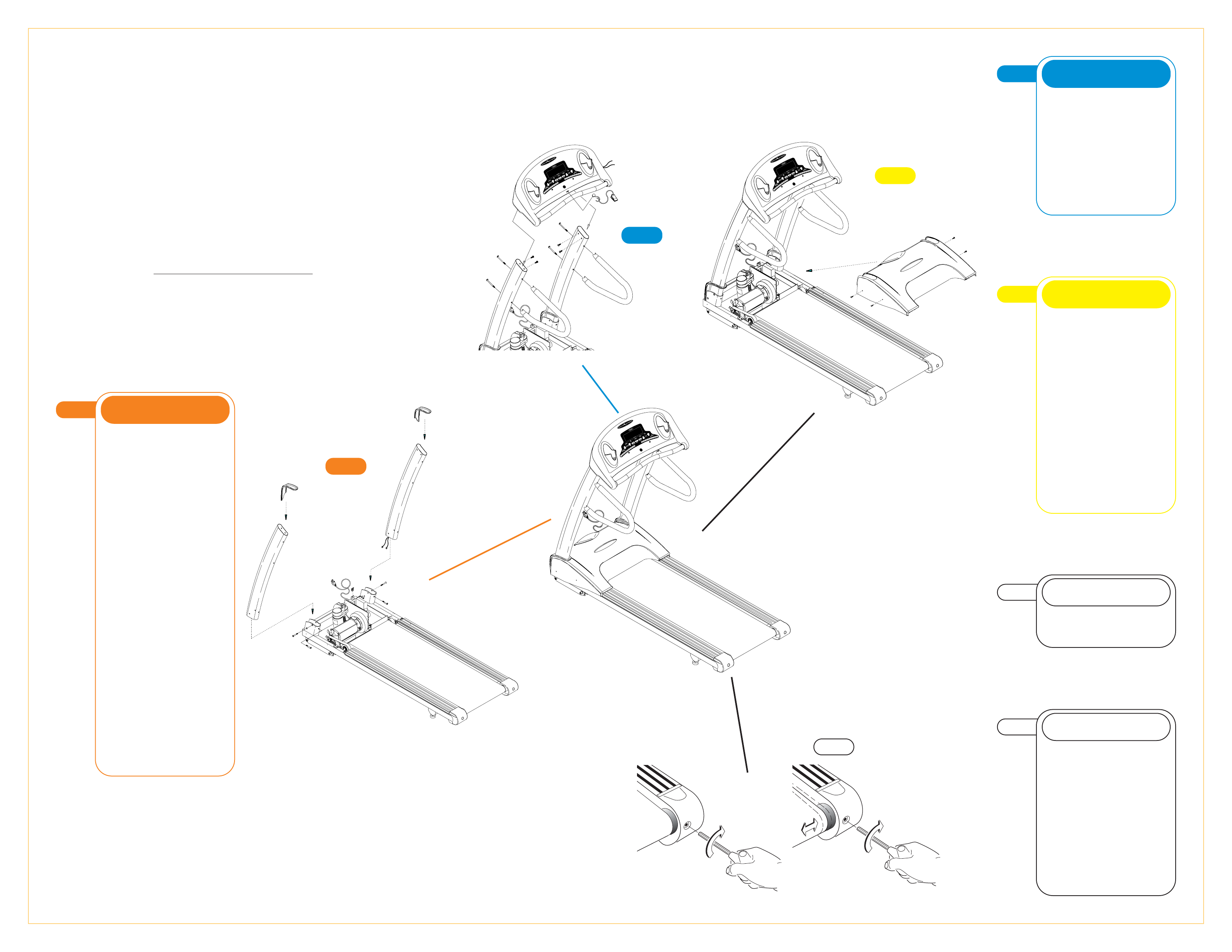
1
STEP
• Slide the rubber covers on to the left
& right console supports, making sure
that the lower cutout is facing inward.
T9700HRT: Slide the data cable
down the right console support using
the white wire tie as a guide. Make
sure that the data (1 large ribbon
cable) goes through the large hole in
the lower part of the console upright.
T9500HRT: Slide the data cables
down the right console support using
the white wire tie as a guide. Make
sure that the data cables (one small
grey & one large black
telephone-style cable) go through the
large hole in the lower part of the
console upright.
• Insert the left console support into
the console support bracket and
secure with two bolts (M8 x 55L
Flathead) in the side of the console
support bracket.
• Insert one bolt (M8 x 20L) in the
rear of the console support bracket.
• Tighten all three bolts with the blue-
handled 5mm Allen wrench.
• Repeat this on the right side.
NOTE: There are no data cables on
the left side.
ORANGE BAG
1
STEP
2
STEP
• Mount the console to the console
mast using four bolts (M8 x 15L) and
tighten with the 5mm Allen wrench.
NOTE: Push all extra data cable into
the console mast. Make sure not to
pinch or cut the data cable.
• Mount the right-hand side mount
handlebar to the console mast using
two bolts (M8 x 135L). Repeat this on
the left-hand side.
BLUE BAG
2
STEP
3
STEP
T9500HRT: Plug in the small data
cable into the small plug connection
on the lower control board. Plug in the
large data cable into the large plug
connection on the lower control
board.
T9700HRT: Plug the large 20-
ribbon cable into the 20-pin
connection on the lower control
board. Slide down the rubber covers
on the left & right console supports.
• Install the motor cover making sure
that the rubber covers are inserted into
the motor cover. Secure the motor
cover using the six (M4 x 12L) screws
(see Yellow bag).
DATA CABLES
5
STEP
T9500HRT AND T9700HRT
5
STEP
• If the running belt slips when used,
use the supplied 8
MM
Allen wrench to
turn the left and right tension bolts
clockwise
1
/
4-turn at a time until the
belt no longer slips.
• If the running belt is too far to the
right side, use the supplied 8
MM
Allen
wrench to turn the right tension bolt
clockwise
1
/
4-turn at a time until the
belt remains centered during use.
If the running belt is too far to the left
side, turn the left tension bolt
clockwise
1
/
4-turn at a time until the
belt remains centered during use.
BELT TENSION
4
STEP
Please refer to back cover for this
procedure, then return to Step 5.
AUTO CALIBRATION
3
STEP