


4
6
3
STEP
4
STEP
1
STEP
4
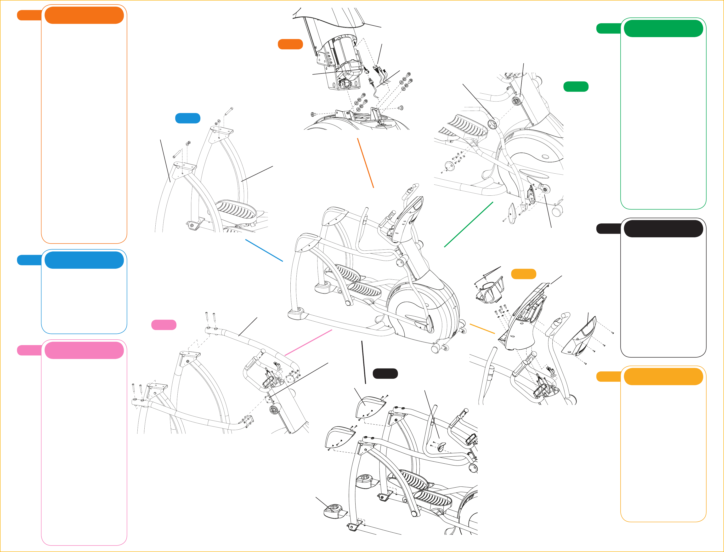
Suspension Arm
2
STEP
2
STEP
• Lift the left incline arm and insert the
bearing end of the suspension arm into
the
bracket of the incline arm. From the
outside,
insert a hex head bolt
(M12x95L)
through the bracket and suspension arm.
Secure with a lock washer (M12) and
nut (M12). Tighten with two 19mm
wrenches. Make sure hardware is tight.
• Repeat this step on the right side.
B L U E B A G S
3
STEP
NOTE: A second person will be helpful
to complete this step.
• Place the left connection arm over the
left incline arm bracket and connect with
two socket head cap bolts (M10x65L).
Tighten only a few turns with the 8mm
L-shaped wrench.
• Insert the pin on the front flange of
the connection arm to the hole in the
console mast elevation bracket.
• Repeat these steps on the right side.
• When the pins of both connection
arms are seated in the holes of the
console mast elevation bracket lift the
entire assembly slightly to line up the
screw holes. Insert four socket head
cap bolts (M8x30L) with washers
(8.2x13x1.4T) through these holes.
Secure with a washer (8.2x13x1.4T)
and nylon nut (M8) to each bolt.
Tighten with the 6mm L-shaped wrench
and 13mm wrench.
• Go back and completely tighten the
screws that connect the connection
arms to the incline arms with the 8mm
L-shaped wrench.
P I N K B A G
1
STEP
NOTE: A second person will be helpful
to complete this step.
• Slide the console mast boot onto the
console mast.
• Locate the data cable and elevation
motor connector in the main frame
recess. Make sure they are pulled out of
the opening and can be easily plugged
in when the mast is inserted.
• Set the console mast into the
console mast frame bracket. Secure the
front of the mast to the frame bracket
with four socket head bolts (M8x20L),
four lock washers (M8), and four flat
washers (8.2x16x1.4T). Tighten with
the 6mm T-shaped wrench. Secure the
sides of the console mast to the console
mast bracket with one flat head bolt
(M8x12L) to each side. Tighten with the
5mm L-shaped wrench.
• Plug in the elevation motor cable to
the cable socket sitting in the frame
bracket.
• Wrap the wire tie that comes out of
the bottom of the console mast around
the data cable that exits the top of the
frame. Feed the wire tie and data cable
up through the channel in the side of the
mast while pulling the wire tie straight up
through the top of the mast.
• Slide the boot down over the frame
and snap in place.
O R A N G E B A G
5
STEP
• Position the covers over the rear
incline arm bracket and secure each
cover in place with four bolts (M5x25L).
• Position the cover over the elevation
bracket and secure with two bolts
(M5x15L) from the RED BAG.
• Take the rear base frame covers and
pull apart to separate and slide around
the bottom of the incline arm. Snap the
three tabs down to set in place.
• Begin pedaling to power up the unit
or plug the power cord into the power
socket in the front of the unit. Plug the
other end of the cord into the wall outlet.
Make sure the power switches at the
bottom of the unit and on the back of
the console are in the on position.
B L A C K B A G S
4
STEP
• Connect the remote toggle cables.
Place the left dual-action arm on the
left rotation housing and secure in
place with four bolts (M8x20L) and
lock washers (M8). Tighten with the
6mm L-shaped wrench.
• Line up the rotation housing cover
over the rotation housing and push to
snap in place.
• Slide the link arm between the
flanges of the dual-action arm
bracket. Insert a socket head cap
bolt (M8x50L) through the hole to
connect the brackets. Secure with
a M8 washer and nylon nut (M8).
Tighten with the 10mm wrench and
5mm L-shaped wrench.
• Set the dual-action cover in place
over the connection bracket. Place the
nut (M5) into the recess on the inside
cover. Insert a bolt (M5x50L) through
the outside hole and tighten to the nut
with a screwdriver.
• Repeat these steps on the right side
with the other green hardware bag.
G R E E N B A G S
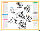
Incline Arm
Connection Arm
Connection
Arm Pin
Rotation Housing
Dual-Action Arm
Link Arm Bracket
Rear Base
Frame Covers
Incline Arm
Covers
Elevation
Bracket Cover
(RED BAG)
Console
Cover
Data Cable
Elevation Motor
Cable
Elevation Motor
Connector
5
STEP
4
A
A
A
6
6
STEP
Console
6
STEP
• Remove the wire tie from the data
cable and console mast.
• Remove the four console mounting
bolts from the backside of the console
with the screwdriver. Connect the heart
rate wires coming from the mast to
the heart rate wires coming from the
bottom of the console. Insert the data
cable through the bottom of the console
and plug into the board. Pull any extra
wire down into the console mast. Secure
console to the bracket using the four M8
x 15L socket bolts.
• Connect 9-volt battery. Position the
rear console cover on the back of
the console and secure with the four
bolts removed earlier. Tighten with the
screwdriver.
• Insert cupholder and attach with 2
M5 x 12L bolts. Snap the end caps
in place.
Y E L L O W B A G
Console Mast Boot
End Caps
S70_AG_091217.indd 2 12/17/09 2:49 PM