


2
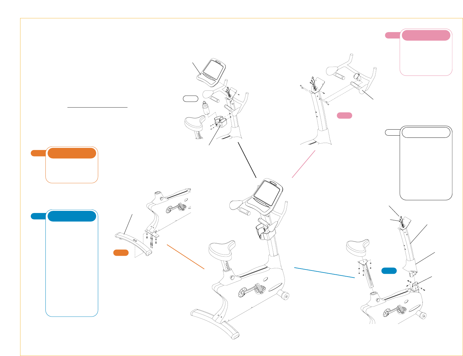
STEP
• Slide the console mast boot onto the
console mast.
• Unfold the wire harness located in
the console mast frame bracket.
Connect it to the wire tie coming from
the bottom of the console mast. Pull
the wire tie and wire harness up
through the top of the console mast
while simultaneously sliding the mast
into the frame bracket.
• Secure the mast to the frame using
six lock washers (M8) and six bolts
(M8x15L). Tighten with the 5mm
T-shaped wrench. Place the seventh
bolt (M8x15L) in the rear of the frame
bracket and tighten until snug.
• Slide the console mast boot down
and set it in place on the side cover.
• Remove the nuts (M8) from the bottom
of the seat. Attach the seat to the seat
post with the nuts you just removed.
Tighten with the 15mm wrench.
BLUE BAG
3
STEP
• Feed the heart rate wires of the
handlebar through the small hole located
in the front of the console mast. Pull
these wires up through the hole at the
top of the console mast. Attach the
handlebar to the console mast using
four bolts (M8x20L). Tighten with the
5mm T-shaped wrench.
PINK BAG
1
STEP
• Install the rear foot with four lock
washers (M8), two inside bolts
(M8x65L), and two outside bolts
(M8x20L). Tighten with the 5mm
T-shaped wrench.
ORANGE BAG
Assembly
Guide
E3700HRT
COMMERCIAL FITNESS BIKE
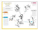
1
STEP
To avoid possible damage to this Fitness Bike, please follow these assembly steps in the correct order.
Before proceeding, find your new Fitness Bike’s serial number located on the front axle tube, and enter here:
Refer to this number when calling for service, and enter this serial number on your Warranty Card and in
your own records. Be sure to read your Owner’s Guide before using your new Fitness Bike.
If any parts, hardware or tools are missing, please call 1.800.335.4348, Extension 12
NOTE: It is recommended that you apply grease to the threads of each bolt and screw as you assemble
your Fitness Bike to prevent loosening and noise. Also, during each assembly step, ensure that ALL screws
and bolts are in place and partially threaded in before completely tightening any ONE screw or bolt.
4
STEP
• Remove the four mounting bolts from
the back of the console with the
screwdriver. Plug in the wire harness
and the two heart rate wires to the
back of the console. Attach the console
to the console mast with the four bolts
removed earlier in this step.
• Remove the battery cover on the
backside of the console. Plug in the 9-
volt battery. Re-attach the battery cover.
• With the screwdriver, remove the two
bolts located half way up the console
mast. Attach the accessory tray to the
console mast with the two bolts.
CONSOLE
3
STEP
4
STEP
Handlebar
Rear Foot
Console Mast
Console Mast
Boot
Frame
Bracket
Heart Rate
Wires
Wire Harness
2
STEP
Accessory
Tray
Console