


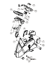
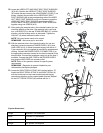
1. Locate the BOTTOM COVER (#6). Position the cover as
shown with the notch of the center hole facing downward.
Slide the BOTTOM COVER down over the UPPER CONSOLE
SUPPORT TUBE (A) until it rests against the FRONT TUBE
EXTENSION (B).
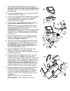
2. Position the HANDLEBAR (#11) as shown near the UPPER
CONSOLE SUPPORT TUBE (A).
3. Connect the 4-PIN HEART RATE CONNECTOR (4P) leading
from the HANDLEBAR (#11) center to the 4-PIN HEART
RATE CONNECTOR (4P) leading from the UPPER
CONSOLE SUPPORT TUBE (A).
4. Carefully slide the HANDLEBAR MOUNTING FLANGES (C)
into the UPPER CONSOLE SUPPORT TUBE (A).
NOTE: Be careful not to pinch the HEART RATE CABLE
when inserting the HANDLEBAR FLANGES (C) into THE
UPPER CONSOLE SUPPORT TUBE (A).
MISE EN GARDE: Faites attention à ne pas pincer le CÂBLE
de FRÉQUENCE CARDIAQUE en insérant les BRIDES de
GUIDON (C) dans LE TUBE SUPÉRIEUR de SOUTIEN de
CONSOLE (A).
5. Secure the HANDLEBAR (#11) to the UPPER CONSOLE
SUPPORT TUBE (A) using four MOUNTING BOLTS (#1).
Tighten the SCREWS to 15-20 ft. lbs.
6. Locate the TOP COVER (#5). Slide the BOTTOM COVER
(#6) upward toward the HANDLEBAR (#11) until it contacts
the HANDLEBAR. Position the TOP COVER over the
HANDLEBAR and align it to the BOTTOM COVER. Secure
the TOP COVER to the BOTTOM COVER using four
PHILLIPS SCREWS (#2) as shown.
7. Align the ACCESSORY TRAY (#3) to the bottom of the
DISPLAY CONSOLE (#4) as shown. Secure the
ACCESSORY TRAY to the DISPLAY CONSOLE using four
PHILLIPS SCREWS (#2).
8. Position the DISPLAY CONSOLE (#4) near the top of the
CONSOLE SUPPORT ASSEMBLY (D). Remove the
protective cover on the COAXIAL CABLE (CX). Carefully align
and connect the COAXIAL CABLE to the coaxial connector
located inside the rear of the DISPLAY CONSOLE. Align the
LOCKING TABS of the 14-PIN CONNECTOR, 5-PIN
CONNECTOR, and the 4-PIN CONNECTOR and plug them
into the matching connectors located inside the rear of the
DISPLAY CONSOLE until they snap securely into place.
9. Carefully feed the wires back into the top of the CONSOLE
SUPPORT ASSEMBLY (D) and attach the DISPLAY
CONSOLE (#4) to the CONSOLE SUPPORT ASSEMBLY
using the four CONSOLE SCREWS (#4) and a Phillips
screwdriver. Tighten the four SCREWS securely in a criss-
cross pattern.
NOTE: Be careful not to over-tighten the screws.
MISE EN GARDE : Veiller à ne pas trop serrer la vis.
7
15
8
F
2
3
4
2
6
C
5
A
4P
4P
D
11
B
1
1
2
CX