


4
OW NER 'S MAN UAL • F53 0
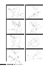
coming out of the handle bar and main beam tube.
Place the seat cushion on the seat plate, line up
the six bolts extending from the bottom of the seat
with the six holes on the seat plate. Using two
M8 nylock nuts, attach the seat to the seat plate
at the two front bolts. Align the four holes of the
handlebar with the four bolts of the seat cushion.
Secure the handlebar and the bottom seat cushion
using four M8 nylock nuts.
SEAT BACK FIG.7
Install the seat back cushion onto the rear seat
bracket using four acorn nuts (closed end nut).
MAIN BEAM TUBE AND
FRONT ASSEMBLY FIG. 8
Connect the wires from the main beam tube and
the front frame assembly. Attach the main beam
tube to the front frame assembly using four M8x20
bolts, two bolts on both sides. NOTE! Be careful
not to damage the wires!
U S E
CORRECT BODY POSITION
The Recumbent Cycle F 530 is designed to
comfortably distribute your weight evenly over
your buttocks and lumbar region of your lower
back. Your legs are also positioned closer to the
level of your heart, allowing a less strenuous and
more efcient cardiovascular workout. To ensure
proper positioning please follow the recommended
guidelines:
ADJUSTING THE SEAT TO
PEDAL DISTANCE
The lenght of the seat rail should be adjusted
so that your knee remains slightly bent (not
completely straight) when your leg is extended to
the furthest pedaling point forward. To adjust the
distance between the seat and the pedals: lift the
lever located below the seat to release the lock. To
extend the distance, push forward with your feet
in the pedals. Backpedal to nd the comfortable
distance. To reduce the distance, pull the front
frame assembly using the scalloped handle next
to the left side crank. Push the lever back to
horizontal position to lock the attachment.
A S S E M B LY
TRANSPORT WHEELS FIG. 1
Insert wheel couplers into front frame assembly,
secure each with an 4x15 screw. Push wheels onto
couplers and secure each with an M6x25 screw and
washer. Cover each bolt by pushing a green end cap
into hole at the center of each wheel.
METER FIG. 2
Put two 1.5 V AA batteries into the battery holder
at the back of the meter, noting the + and - marks
on the bottom of the holder. Remove the wire
tying the meter wire on the bracket support tube.
Route the meter wire through the meter bracket.
Press the meter bracket into the bracket support
tube and line up the screw holes between the meter
bracket and the bracket support tube. Secure with
an M4x15L self-taping screw. Connect the meter
wire to the plug on the back side of the meter.
Tuck the wire inside the meter and carefully slide
the meter onto the meter bracket. NOTE! Be
careful not to damage the meter wire! Remove the
protecting lm from the display.
PEDALS FIG.3
The pedals are distinguished by the markings R
and L on their shafts (R = right, L = left). Fasten
the right pedal to the right pedal crank turning
clockwise and the left pedal to the left pedal crank
turning counterclockwise. Fasten the pedal straps.
Choose the strap tightness, set the appropriate
strap hole on the retainer from below and pull
forcibly upward. The pedal straps are adjustable.
Especially when the device is new, the fastening of
the strap may seem relatively tight.
FEET FIG.4
Insert a foot coupler into each side of rear frame
cross tube. Secure each with a 4x15 screw. Push feet
onto couplers.
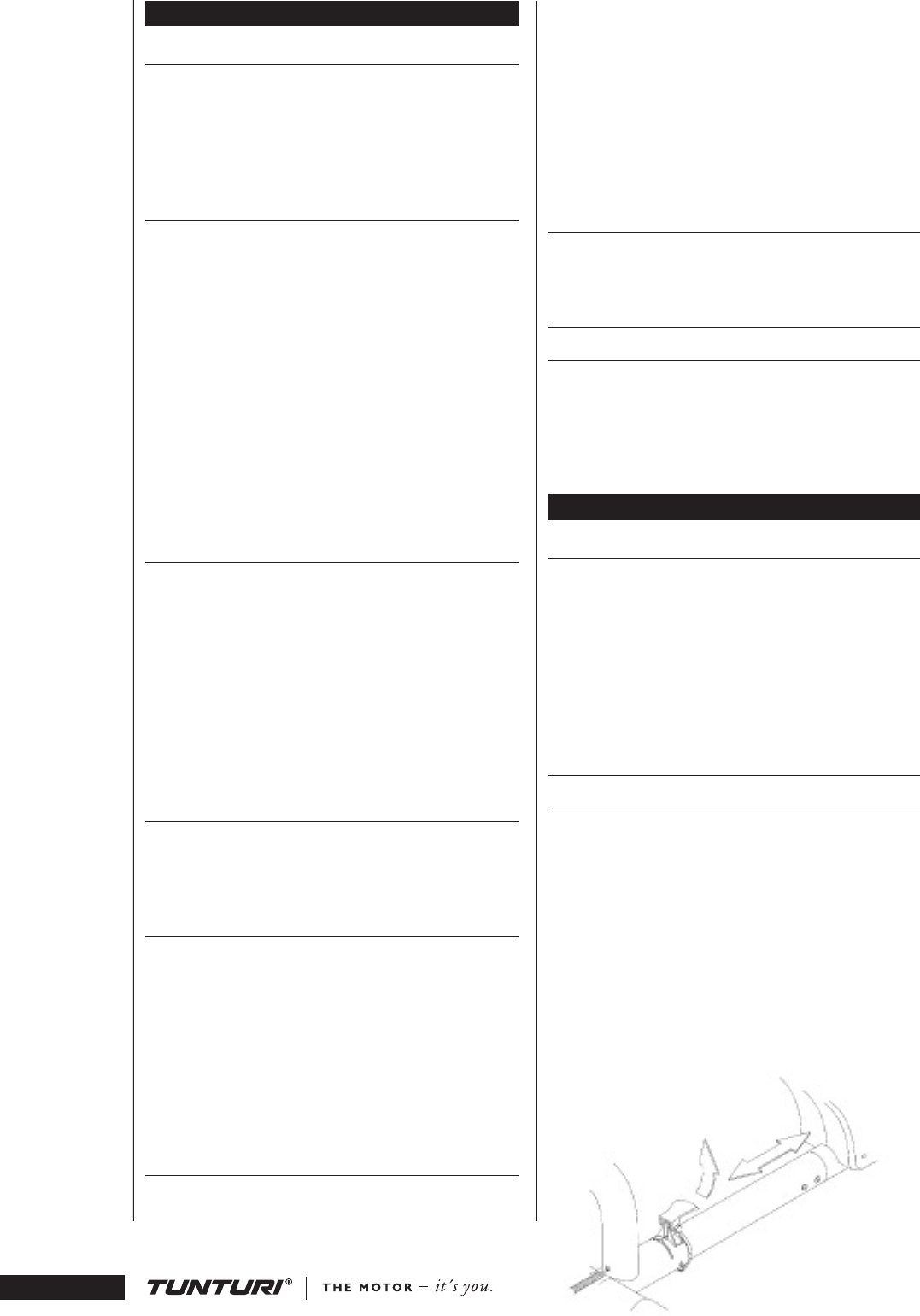
MAIN BEAM TUBE FIG. 5
Insure that the seat adjustment lever is in the
release (upward) position. Loosen the plastic
bushing at the back end of the main beam tube and
pull the pulse cable through the main beam tube
using the pulling string. Slide the main beam tube
through the seat frame assembly tube.
Place the plastic bushing around the pulse
cable and push the bushing back to its place in the
hole at the back of the main beam tube.
HANDLEBAR AND SEAT CUSHION FIG.6
Position the handlebar so that it rests on the
supports of the seat plate. Connect the cables