Page 8
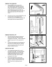
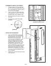
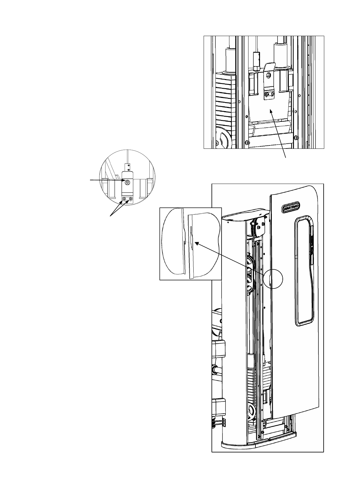
GAP
SCREWS
INCREMENTAL WEIGHT ADJUSTMENT:
1. Check to make sure the gap between
the TOP PLATE pin and the 20mm hole
of the INCREMENTAL WEIGHT plate is
3mm or less when engage.
2. If gap is greater than 3mm, loosen but
do not remove the two BUTTON HEAD
SCREWS (M6) using a 4MM hex key.
3. Slide the bracket up or down to create a
3mm gap.
4. Re-tighten the two BUTTON HEAD
SCREWS.
INCREMENTAL WEIGHT PLATE
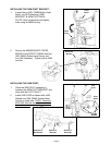
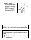
INSTALLING THE SHROUDS:
1. Insert the SHROUDS from the top
sliding downward. The SHROUDS
have seven hooks for mounting.
Before the shroud can be slide
down into place the SHROUD hooks
need to be aligned with the corres-
ponding mounting slots found on the
weight frame of the equipment. Once
the SHROUD hooks are in the slots,
slide the SHROUD into place and verify
that the top of the SHROUD is aligned
with the top of the weight stack. If the
SHROUD is not aligned use the palm of
your hand and tap the SHROUD down
until it is aligned.
2. Repeat step 1 with the inside shroud and
verify alignment.


