


S
STAR
TRAC
E
SERIES
BIKES
OWNER’S
MANUAL 15
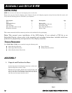
ASSEMBLY- LED DISPLAY
Your Star Trac Bike will be shipped with the display in a separate carton. This section covers the final assembly of the
LED display. If you ordered a Personal Viewing System (PVS) or an embedded computer, please refer to the separate
assembly instructions included with those products
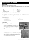
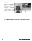
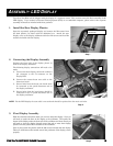
1. Install the Rear Display Plastics
Open the separately packaged display and remove the M4 screws from
the back plastics, set these aside for additional use. Attach the rear
display cover to the display weldment with four M4 screws and four M4
washers included with the display.
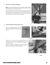
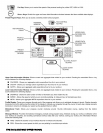
2. Connecting the Display Assembly
Position the front half of the display plastic in
front of the display weldment.
The following display connections will need to be
made.
A. Connect the main display cable with a white 9
pin connector to the J4 connector on the
display PCB.
B. Connect the contact heart rate cable to the
heart rate board
C. Ground wire from the heart rate board must
be connected to the quick disconnect tab on
the display weldment.
D. Ground wire from the base frame should be
connected to the 2
nd
quick disconnect tab on
the display weldment.
NOTE: For the LED display the coax cable is not used and should be replaced into the main neck tube.
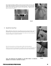
3. Final Display Assembly
With the electrical connections made you can now attach the display. Next you
will need to attach the front of the display to the weldment. First guide the
bottom of the display under the front tabs of the weldment and then second you
will need to pivot the display forward around the tabs to mate front display
plastic to the rear plastic that is attached to the weldment.
Once in place attach the plastics with the M4 screws included with the display.
There are 8 M8 screws that attach around the perimeter of the display, secure
properly.
Step 5
A
B
Quick Disconnect
Ground Tab
Step 2
Step 3
Step 1