


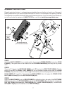
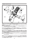
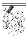
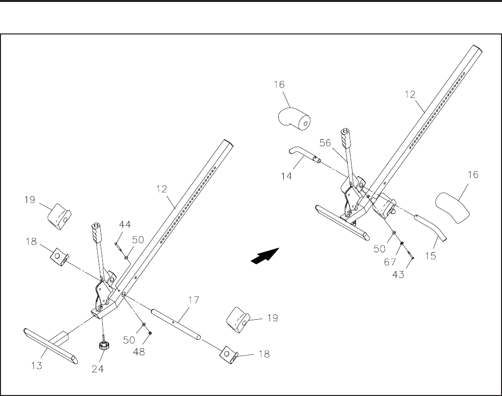
STEP 4
Attach the FOOTREST(13) onto the HEIGHT ADJUSTMENT BEAM(12) with the ADJUSTMENT KNOB(24).
NOTE:
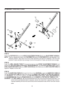
STEP 5
Insert the HEEL HOLDER TUBE(17) through the hole on the HEIGHT ADJUSTMENT BEAM(12) and
secure with HEX BOLT(M6x1x47mm)(44), WASHERS(M6)(50), and NYLOCK NUT(M6x1)(48). Place a
HEEL HOLDER BRACKET(18) onto a HEEL HOLDER(19), then slide them onto HEEL HOLDER TUBE(17)
together. Repeat on other side.
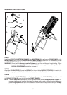
STEP 6
Insert the OUTER PAD TUBE(15) through the hole on the LEVER(56). Insert the INNER PAD TUBE(14)
into the OUTER PAD TUBE(15). Align the holes on the INNER PAD TUBE(14), OUTER PAD TUBE(15),
and LEVER(56), then bolt them together with HEX BOLT(M6x1x42mm)(43), LOCK WASHER(M6)(67),
and WASHER(M6)(50). Slide the FOAM PADS(16) onto the INNER and OUTER PAD TUBES(14, 15).
WARNING:
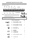
ASSEMBLY INSTRUCTIONS
8
The PAD TUBES(14, 15) must be assembled with the ends pointed downward as shown. The
ends must be pointed downward to properly secure the users feet in place during inversion.
Improper assembly will allow the user's feet to come loose and the user will fall from the inversion
table.
The four adjustment holes in the FOOTREST(13) allow the FOOTREST(13) to be attached in four
different positions. Start with one of the center positions and adjust if necessary. Use the outer
position if users are taller than average. Use the inner position if users are shorter than average.