


ASSEMBLY INSTRUCTIONS
9
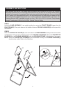
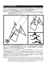
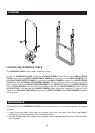
STEP 5
Attach the FOOTREST(8) onto the HEIGHT ADJUSTMENT BEAM(6) with BOLTS(M8x1.25x50mm)(34),
WASHERS(M8)(38), and NYLOCK NUTS(M8x1.25)(36).
NOTE:
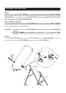
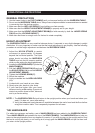
STEP 6
Insert the PAD TUBE(9) through the hole on the HEIGHT ADJUSTMENT BEAM(6) and secure with
BOLT(M6x1x45mm)(32) and NYLOCK NUT(M6x1)(35). Place a HEEL HOLDER BRACKET(10) onto a
HEEL HOLDER(11), then slide them onto PAD TUBE(9) together. Slide another set of HEEL HOLDER
BRACKET(10) and HEEL HOLDER(11) over the other end of the PAD TUBE(9).
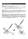
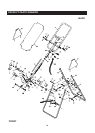
STEP 7
Attach the ADJUSTABLE INSTEP FRAME(7) to the HEIGHT ADJUSTMENT BEAM(6) by pulling the
SMALL SPRING PIN(13) and sliding the ADJUSTABLE INSTEP FRAME(7) completely into the HEIGHT
ADJUSTMENT BEAM(6). Insert the BOLT(M6x1x45mm)(32) halfway through the square tube on the
HEIGHT ADJUSTMENT BEAM(6), slide the bolt through the ring at the bottom of the SPRING(12), slide the
bolt through the square tube and secure with NYLOCK NUT(M6x1)(35). Press the SQUARE PLUG(40) into
the HEIGHT ADJUSTMENT BEAM(6). Install a HEEL HOLDER BRACKET(10) and HEEL HOLDER(11)
onto both sides of the ADJUSTABLE INSTEP FRAME(7).
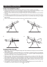
The ve holes in the FOOTREST(8) allow the FOOTREST(8) to be attached in three different
positions. Start with the center position and adjust if necessary. Use the outer position if users are
taller than average. Use the inner position if users are shorter than average.