


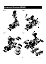
XE100 / XE200 / XE300 Elliptical
18
STEP 2: HANDLE BAR ASSEMBLY
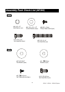
1. Install the two 28m/m Wave Washers (81) onto the Left and Right side of the Handle Bar axle.
2. Slide the Left (10) and Right (11) Handle Bars onto the appropriate side of the axle. The
handlebars have a small sticker on them indicating L (left) and R (right).
3. Put the two 3/8 X 30mm Flat Washers (97) onto the two 3/8 X 3/4 Hex Head Bolts (103) and
install, and tighten, in the threaded holes in the ends of the axle.
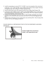
4. Connect the two wires together (124, 125) and store the excess, including plastic connectors,
back into the console mast. Place the rubber grommet (123) over the wire and snap it into the
hole in the console mast.
5. Install the Front Handle Bar Covers (54-1 left, 55-1 right) and Rear Handle Bar Cover (54 left,
55 right) over the Handle Bar axle connections with the six 3.5x10m/m Self Tapping Screws
(87).
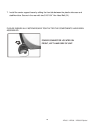
STEP 3: CONNECTING ARM ASSEMBLY
1. Align the hole in the rod end of the left Connecting arm (8) with the hole in the bracket of the
left Handle Bar (10). The rod end should be on the inner side of the Handle Bar bracket. Make
sure the ty-wrap is removed from the rod end and the sleeve spacer (22) does not fall out
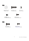
during assembly. Take one 5/16" x 1-1/4" Hex Head Bolt (104) and install it through the Handle
Bar bracket and the rod end. Install one 5/16" x 20 x 1.5T Flat Washer (80) and one 5/16" x
7mm Nylon Nut (71) on the 5/16" x 1-1/4" Hex Head Bolt (104) and tighten as tight as possible
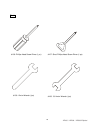
using the two12m/m Wrenches provided. Repeat the procedure for the right side Pedal
/Connecting Arm.
2. Install the connecting arm covers (57,57-1 & 58,58-1) over the connection of the rod end and
handle bars (10 & 11) with eight M5 x 15m/m Phillips Head Screws (105) and eight 3.5x12m/m
self tapping screws (87) by using the phillips head screw driver.
3. Install the front (122) and rear (121) console mast covers with three M5 x 15m/m Screws (105)
and two 3.5x12m/m Self Tapping Screws (87).
STEP 4: COVER ASSEMBLY
1. Install the two Wheel Covers (52) using the four M5x15m/m Phillips Head Screws (105).
2. Install the front stabilizer cover (49) with the two M5 x 15m/m Phillips Head Screws (105).
3. Install the six L-brackets (149), for the steel shroud, using twelve M5x15mm Philips Head
Screws (84).
4. Install the two W-shaped brackets (148) from under the aluminum tracks and insert the
5/16x3/4 Hex Head mounting screws (91) from above the aluminum tracks, into the brackets,
and tighten them with a 12mm wrench.
5. Remove the ten screws (105) that hold the front covers (Left,150-3 & Right,151-3) to the two
steel shrouds (150 & 151) and remove covers (they will be re-installed later).
6. Lift the pedal arms and slide the steel shrouds over the wheels and onto the real rails, lining
them up with the mounting brackets installed earlier. Secure the steel shrouds to the brackets
with eight M5 x 15m/m Phillips Head Screws (105). Re-install the front covers removed in step
5 with the ten screws (105).