


15
10/05 ID# M88724C
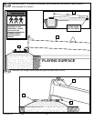
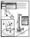
14.
A.
B.
15.
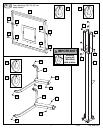
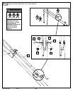
Apply height indicator
labels (32 & 31) to height
indicators (30).
2.
4.
3.
1.
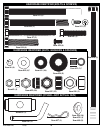
Install net (4) to rim as shown.
7
8
9
10
7
8
9
10
78
9
10
78
9
10
7
8
9
10
7
8
9
10
78
9
10
7
8
9
10
78
9
10
7
8
9
10
7
8
9
10
7
8
9
10
7
8
9
10
7
8
9
10
7
8
9
10
7
8
9
10
78
9
10
78
9
10
7
8
9
10
7
8
9
10
78
9
1
0
7
8
9
10
78
9
10
7
8
9
10
7
8
9
10
7
8
9
10
7
8
9
10
7
8
9
10
7
8
9
10
7
8
9
10
78
9
10
78
9
10
7
8
9
10
7
8
9
10
78
9
10
7
8
9
10
78
9
10
7
8
9
10
7
8
9
10
7
8
9
10
7
8
9
10
7
8
9
10
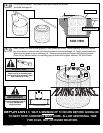
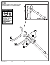
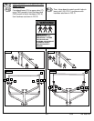
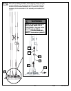
IMPORTANT!
NOTE ORIENTATION
OF HEIGHT
INDICATORS:
10’
MARK SHOULD
FACE AWAY FROM
BACKBOARD.
Set-up For Right SideSet-up For Left Side
7
8
9
10
7
8
9
10
78
9
10
78
9
10
7
8
9
10
7
8
9
10
78
9
10
7
8
9
10
78
9
10
7
8
9
10
7
8
9
10
7
8
9
10
7
8
9
10
7
8
9
10
29
29
32
31
30
30
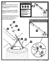
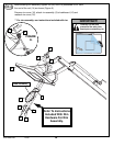
Attach height indicators to lower yoke in area shown by turning
screws (29) into place with a Phillips head screwdriver. Apply name
plate sticker (27) to lower yoke as shown.
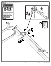
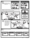
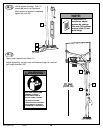
Attach height indicators
to lower yoke in area
shown by tapping
screws (29) into place
with a rubber mallet.
Apply name plate
sticker (27) to lower
yoke as shown.
C
27
27