


12/05 ID# M881111
19
20
19
38
37
21
18
14.
20
15.
16
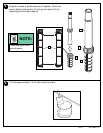
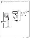
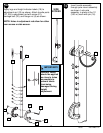
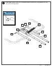
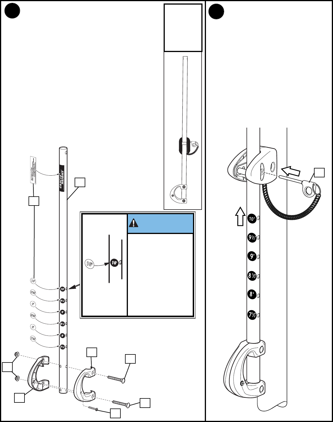
Insert handle assembly
through pole mount assembly
as shown. Lock pole
assembly in place at the 10’
(3.05 m) mark with pin (16).
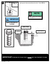
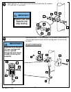
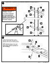
Apply logo and height indicator labels (19) to
adjustment rod (18) as shown. Attach handle parts
(37, 38) to adjustment rod with screw (21),
carriage bolt (20), and flange nut (8) as shown.
NOTE: Holes in adjustment rod allow for either
rear access or side access.
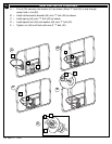
8
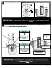
SIDE
ACCESS
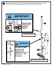
Indicator labels
should be applied
as close to holes
as possible to
prevent labels
from being
damaged during
height
adjustment.
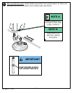
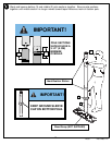
IMPORTANT!: