


8
P/N 214949B 05/03
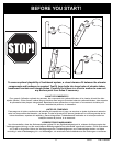
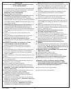
INSTRUCTIONS
IMPORTANT! WRITE MODEL NUMBER FROM BOX ONTO PAGE 1
OF THIS OWNERS MANUAL
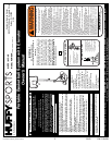
1. Install wheel axle (6) through wheel carriage (63) and install wheels
(5) onto wheel axle (6) with spacers (64) as shown. Secure wheel
bracket as shown, a deep socket is recommended.
IMPORTANT! DO NOT OVER TIGHTEN.
2. Mark pole sections with tape as shown.
3. IMPORTANT! Center alignment slot of middle pole section (2)
in a lower hole of top pole section (1) as shown. While
maintaining alignment, bounce pole top (1) and middle section (2)
together as shown until they no longer move toward taped reference
mark. Upright assembly. NOTE: Pole sections should have a 3-1/2”
(9 cm) minimum overlap.
4. IMPORTANT! Center alignment slot of lower pole section (3) in
a lower hole of middle pole section (2) as in step 3. While
maintaining alignment, bounce assembly and lower section (3)
together as shown until they no longer move toward taped reference
mark. NOTE: Pole sections should have a 3-1/2” (9 cm) minimum
overlap.
5. Install rod (7) through holes in bottom pole section (3) and
eyebolt (8).
6. Insert pole assembly into tank assembly as shown. Secure pole
assembly with upper pivot bracket (9) and lock nut (10).
IMPORTANT! Two people recommended for this step.
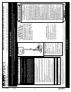
7. Secure base struts (11) to pole using bolt (12) washers (13) and nut
(15) as shown.
WARNING: TIGHTEN BOLT (12) IN LOCK NUT (15) UNTIL
FLUSH (EVEN) WITH LOCK NUT’S OUTER EDGE.
Rotate the non-secured ends of base struts (11) as shown.
8. Secure base struts (11) to base using bolt (16) washers (13)
and nut (14).
9. Insert carriage bolts (18) into middle set of holes on wheel bracket
(21) as shown. Attach lower pivot bracket (17) to wheel bracket
using bolt (18), washers (13), disc (28), and nut (10) as shown.
Tighten completely.
10. Attach handle bar (20) to wheel bracket assembly using nuts (14) as
shown.
11. Install wheels (3) onto axle (24) and wheel bracket assembly with
push caps (25) as shown.
12. Attach wheel bracket assembly to base assembly using bolt (19),
washers (13), and nut (10) as shown.
13. Carefully reposition entire assembly as shown.
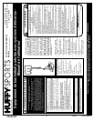
14. Attach front of plastic handle (26) to back of plastic handle (23)
around handle bar (20) using self- tapping screws (27) as shown.
IMPORTANT! Front of plastic handle (26) should face outward,
away from pole assembly.
15. Insert bolts (66) through plastic handle assembly, handle bar (20),
and attach nuts (14) as shown. Tighten completely.
IMPORTANT! Two people recommended for this step.
16. Install pole mount bracket (53) with carriage bolts (54) as shown.
Tighten flange nuts (14) completely.
17. Attach spacers (55, 56) to pole mount bracket (53) with bolts (33),
washers (57), and nuts (34) as shown. IMPORTANT! Tighten until
washers (57) no longer move.
18. Attach covers (58) onto pole mount bracket (53) with carriage
bolt (39) and nut (14) as shown. IMPORTANT! Loop end of pin
lanyard (59) over carriage bolt (39) during this assembly.
NOTE: Assemble lanyard (27) to locking pin (28) as shown.
19. Apply logo and height indicator labels (52) to adjustment rod (51) as
shown. Attach handle parts (48, 49) to adjustment rod (51) with
screw (50), carriage bolts (22), and flange nuts (14) as shown.
NOTE: Holes in adjustment rod allow for either rear access or side
access.
20. Insert handle assembly through pole mount assembly as shown.
Lock pole assembly in place at the 10’ (3.05 m) mark with
pin (60).
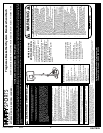
21. Attach backboard support brackets (29) to the backboard frame
using bolts (33), spacers (30), and nuts (34) as shown.
22. Attach lower elevator tubes (35) and spring (42) to backboard
support brackets (29) using spacers (32), bolt (36), and nut (38) as
shown. NOTE: Rim mounting nuts and bolts (31) supplied with rim
hardware.
23. Attach upper elevator tubes (40) to backboard support
brackets (29) using spacers (32), bolt (36), and nut (38) as shown.
24. Support pole on sawhorse. Attach backboard assembly to top pole
section (1). Install pole cap (41).
IMPORTANT! Two people recommended for this step.
Use caution; elevator assembly is heavy.
25. Install handle assembly to lower elevator tubes (35) using
bolt (36), spacers (37) and nut (38). NOTE: Before going onto the
next step, set adjustment system to the 10’ (3.05m) setting.
26. Insert bolt (36) through the left side upper elevator tube (40), then
stretch spring (42) onto bolt (36). Insert bolt (36) through the right
side upper elevator tube (40) and secure with nut (38).
WARNING: USE EYE PROTECTION WHEN INSTALLING
SPRINGS.
27. Roll completed assembly to desired playing area. Secure assembly
to ground using T-Strap (45) and tie down stake (46). Fill tank with
34 gallons of water. IMPORTANT! Add two gallons (7.6 Liters) of
non-toxic antifreeze in sub-freezing climates.
WARNING: DO NOT LEAVE ASSEMBLY UNATTENDED WHEN
EMPTY, MAY TIP OVER.
28. While holding handle, remove pin (60).
29. Move elevator up or down to desired height.
30. Replace pin full length to lock system at desired height.
WARNING: DO NOT ALLOW CHILDREN TO ADJUST HEIGHT.
31. Apply height and moving label (47) to front of pole as shown.
WARNING: USE OF THIS PRODUCT WITHOUT PROPER
INSTALLATION OF SMART CLIPS, OR WHEN ALL SMART
CLIPS ARE NOT PRESENT COULD RESULT IN BODILY HARM.
BE SURE TO FOLLOW DIRECTIONS CAREFULLY.
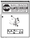
32. Install net clips as shown. (See illustration)
33. Install net as shown. (See illustration)