


Before proceeding to step 11 please complete the
following steps. Failure to do so could lead to
damage to the handgrip heart rate wires!
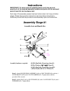
1) Remove END CAP (#11) from the end of the seat rail. The coiled wire seen
above the seat rail needs to be re-routed out the back of the seat rail .
2) Pull the wire from the back of the seat rail until the male prong is flush with
the front of the seat rail. Connec e cables from MAIN UNIT and Seat Rail.
Tape can be used around the attachment of the two cable ends to ensure that
they do not become disconnected.
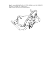
3) Gently pull the excess cable f of the seat tube so that the cable
running through the seat rail is taut. Be careful not to pull apart the cable
connection you have just made. Slide the seat rail with seat assembly gently
into the main unit, while pulling the cable tight from the back of the seat rail.
Slide the seat rail slowly into the main unit. Using a flashlight check to make
sure that the cable is not
- IMPORTANT -
t th
rom the back
protruding from the bottom of the seat rail as it slides
into main unit. CAUTION! If the wire is protruding from the bottom of
the seat rail it may be severed or damaged when the seat rail is fully
inserted into the main unit! This may result in a non-functioning
handgrip heart rate. Carefully slide the seat rail until the slots in the side of
the rail line up with the holes in the main unit.
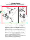
to AIN
LT
OVER (23) ver B LTS (
Ste h 2
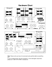
90mm LONG BOLTS (#24), 2 CURVED WASHERS (#19), and 2 ACORN NUTS
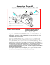
tep 12b: Feed the excess coiled wire from the back end of the seat rail through the hole
n top of the seat rail until about 6 inches of coiled wire is on the outside of the seat rail.
ttach the end of the wire to the back of the handlebar assembly. Feed the remaining
xcess wire into the seat rail and replace the end cap on the end of the seat rail. After
ompleting assembly stage 5 verify that the handgrip heart rate works by hitting manual
art and then placing your hand on the grip heart pad located on the handlebars. Verify
at a heart rate registers on the computer panel after several seconds.
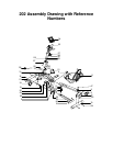
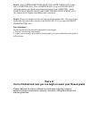
Step 11: Attach SEAT RAIL (#9) M UNIT (#31) with 4, 16 mm BOLTS (#22)
and 4 FLAT WASHERS (#7). Again do not tighten until after step 12. Place BO
C S o O #22) in MAIN UNIT (#31).
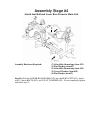
p 12: Attach REAR STABILIZER TUBE (#10) to BASE FRAME (#32) wit
(#20). Tighten with provided wrench. Tighten Allen bolts from steps 10 and 11 with
provided Allen wrench.
S
o
A
e
c
st
th