


-- 13 --
Trouble-Shooting Guide
How the Patented ProSpot Fitness® System Works:
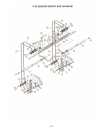
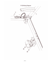
Starting from the Computer Brain, a signal is sent from the left & right side, thru the L & R Grey Base
Frame Wire Harness (white lead), to the Spiral Cord Harness (brown lead), to the Slider Block Cable
Knuckle connector, to inside Barbell Cable to the Sensor on the Barbell. When skin contacts is made
with Barbell Sensors, the signals return to the Computer Brain, at which a 12-volt charge is sent via the
wire harness's (red & black leads), to the solenoids, to release the spring loaded Slider Block Locking
Pins when the Barbell is lifted, allowing the Barbell to move up and down. When skin contact with
Barbell Sensor is broken by either hand, the Computer Brain reads this and stops the 12-volt charge to
the solenoids, at which time, the spring loaded Locking Pins instantaneously engages the hole on the
Guide Post and locks the Barbell from any downward movement.
ALWAYS REMEMBER: After performing any service on the unit, RESET the Computer
on your ProSpot system before using it. Just unplug the power supply Electronic Box, wait 30
seconds and plug back in. Resetting the Computer allows it to recalibrate and work to its greatest
efficiency.
Electrical Service Inspection Checklist:
1. Check for proper functioning of wall receptacle. (Test plug for power)
a. If bad, find new AC power supply.
2. Check wall transformer connection to Electronic Box. Should not be bent or loose.
a. If bad, replace Electronic Box.
3. Check for green flashing light, the indication power to Electronic Box.
a. If no green light, test 12V Wall Adapter for 12-17 volts output.
4. Inspect white connectors from Gray Base Frame Wire Harness connection on Electronic Box
for loose wires.
a. If loose, plug in tight.
b. If broken, replace Gray Base Frame Wire Harness.
5. Inspect Gray Base Frame Wire Harness for possible pinching in frame during assembly.
a. Replace Gray Base Frame Wire Harness if damaged or defective.
6. Inspect Gray Base Frame Wire Harness connection to Spiral Cord Harness.
a. If loose, plug in tight.
b. If broken, replace Gray Base Frame Wire Harness or Spiral Cord Harness.
7. Inspect Spiral Cord connection to Solenoids, Red and Black.
a. If loose, plug in tight.
b. If broken, replace Spiral Cord Harness.
8. Inspect Spiral Cord Brown Lead Sensor Cable Knuckle plug.
a. If loose, plug in tight.
b. If broken, replace Spiral Cord Harness.
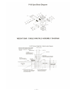
9. Check contact of Sensor Collar Brass Pin with Cable Knuckle plate.
a. If no contact, adjust Sensor Collar closer. (See Weight Bar / Cable-Knuckle Assembly
Diagram)