


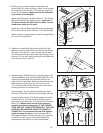
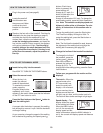
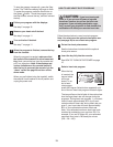
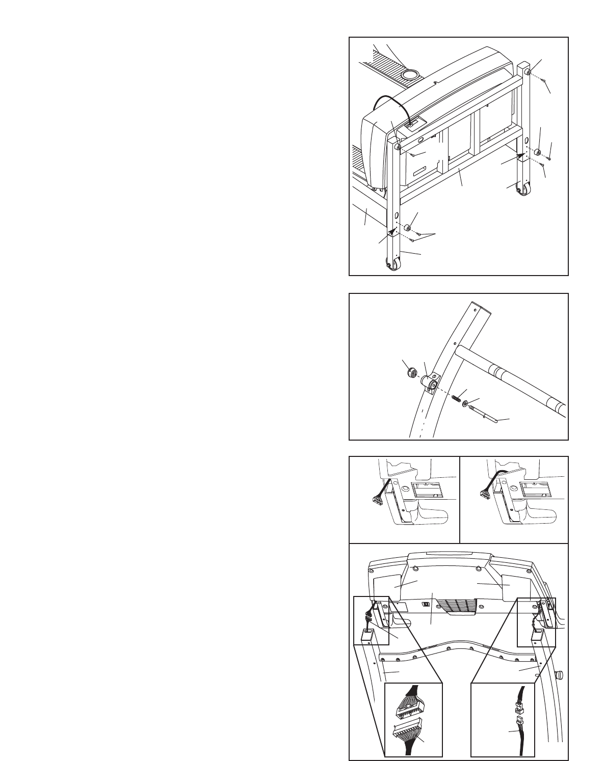
3. Remove the Latch Knob (88) from the Latch Pin (84).
Make sure that the Latch Pin Collar (56) and the Spring
(34) are on the Latch Pin. (Note: If there are two Latch
Pin Collars, place one on each side of the Spring.) Insert
the Latch Pin into the Latch Housing (82) and tighten the
Latch Knob onto the Latch Pin.
88
34
56
84
82
3
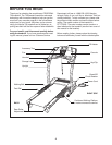
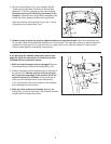
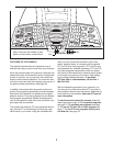
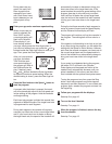
4. See drawing 4c. With the help of a second person, hold
the Console Base (101) near the Uprights (80, 84). Look
under the Console Base and locate the wires on the
sides of the Console Base. Make sure that the wires are
not routed through the openings for the Trays (109,
111). Drawing 4a shows the correct route for the wires.
Drawing 4b shows an incorrect route.
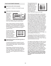
See drawing 4c. Cut the plastic ties holding the Wire
Harness (74) and the pulse wire in the Uprights (80, 84).
Locate the Wire Harness (74) and the pulse wire in the
Uprights (80, 84). Connect the Wire Harness and the
pulse wire to the connectors on the sides of the Console
Base (101). Make sure to connect the connectors
properly (see the inset drawings). IF THE CONNEC-
TORS ARE NOT CONNECTED PROPERLY, THE CON-
SOLE MAY BE DAMAGED WHEN THE POWER IS
TURNED ON. The connectors should slide together
easily and snap into place. If the connectors do not
slide together easily and snap into place, turn a connec
-
tor and try to insert it again. Insert the excess Wire
Harness and pulse wire up into the Console Base.
101
111
109
80
84
4c
74
Pulse
Wire
6
4a
4b
Correct
Incorrect
74
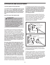
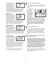
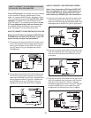
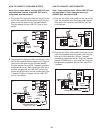
2. With the help of a second person, carefully tip the
Upright Base (97) down as shown. (Note: It may be help
-
ful to place your foot on one of the Extension Legs [92]
as you tip the Uprights.)
Make sure that the Extension
Legs remain in the Uprights.
Attach each Extension Leg (92) with four 1” Tek Screws
(80) and two Base Pads (99) as shown. Tighten the 1”
Tek Screw without the Base Pad first. Note: The indi-
cated center holes are not used.
Attach the other two Base Pads (99) to the Upright Base
(97) in the locations shown with two 1” Tek Screws (80).
With the help of a second person, raise the Upright Base
(97) to the vertical position.
80
80
80
99
92
80
80
92
97
99
Not Used
Not
Used
97
2
99
99