


6
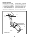
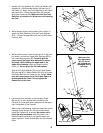
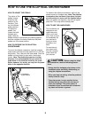
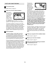
1. Identify the Front Stabilizer (3), which has Wheels (32)
attached to it. While another person lifts the front of
the Frame (1), attach the Front Stabilizer to the Frame
with two M10 x 112mm Carriage Bolts (34) and two
M10 Nylon Locknuts (29). Make sure that the Front
Stabilizer is turned so the Wheels are not touching
the floor.
3
29
32
32
34
1
1
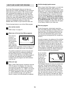
2. While another person lifts the back of the Frame (1),
attach the Rear Stabilizer (4) to the Frame with two
M10 x 112mm Carriage Bolts (34) and two M10 Nylon
Locknuts (29).
34
4
1
3
2
86
87
1
63
83
70
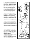
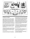
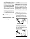
3. While another person holds the Upright (2) in the posi-
tion shown, connect the Upper Wire Harness (86) to
the Lower Wire Harness (87). Carefully pull the
upper end of the Upper Wire Harness to remove
any slack. While holding the upper end of the
Upper Wire Harness, insert the Upright into the
Frame (1). Do not pinch the Wire Harnesses.
Slide an M10 Split Washer (70) and a Frame Spacer
(83) onto the M10 x 88mm Button Bolt (63), and insert
the Button Bolt into the Frame and the Upright. Make
sure that the concave end of the Frame Spacer is
turned toward the Frame. Do not tighten the
Button Bolt at this time.
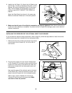
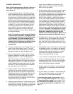
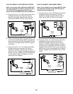
4. Connect the wire harness on the Handgrip Pulse
Sensor (81) to the indicated wire harness on the
Console (5). Insert both wire harnesses into the open-
ing in the bottom of the Console.
Refer to the inset drawing. Insert the metal tube on the
Handgrip Pulse Sensor (81) into the metal bracket
inside the Console (5) as shown. Be careful not to
pinch the wire harnesses. Align the holes in the
metal tube with the holes in the metal bracket, and
tighten two M4 x 16mm Screws (66) into the indicated
holes.
81
5
Wire Harnesses
66
5
Bracket
81
4
2
29
29
Tube
66
Make sure the
Wire Harnesses
(86, 87) do not
get pinched and
damaged during
this step.