


6
3.
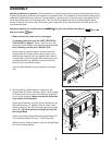
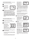
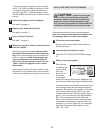
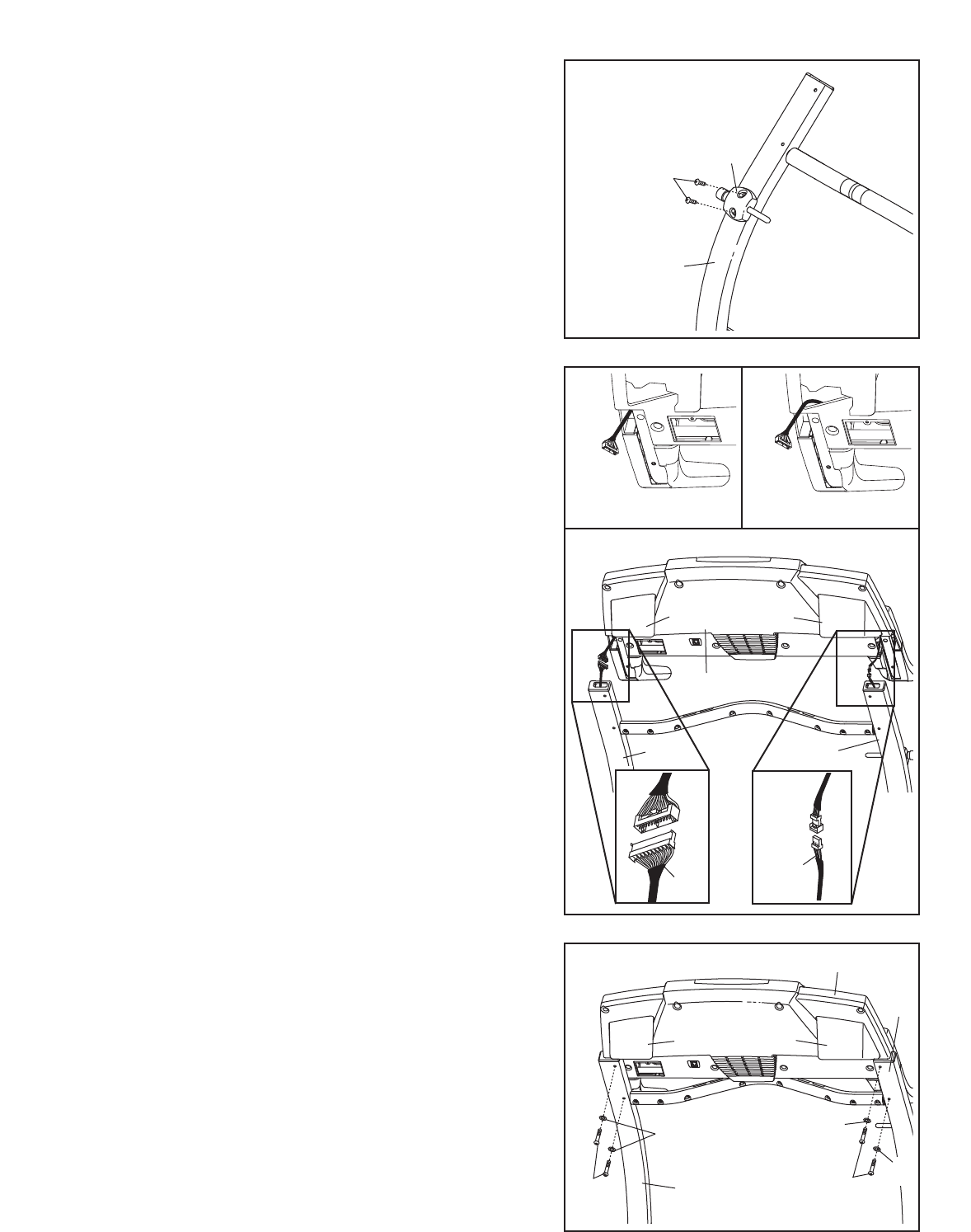
Attach the Latch Assembly (82) to the Left Upright (84)
with the two Latch Screws (46). Start both Latch Screws
before tightening either of them. Note: The Latch Screws
may be preattached to the Left Upright.
46
84
82
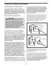
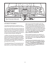
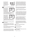
5. Set the Console Base (101) on the Uprights (80, 84). Be
careful not to pinch the Wires (not shown) in the
Uprights. Attach the Console Base to each Upright with
two Console Bolts (76) and two Internal Star Washers
(77); start all four Console Bolts before tightening any of
them.
Make sure that the Left and Right Trays (109, 111) are
pressed into the Console Base (101).
76
77
101
76
77
111
109
80
84
5
3
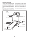
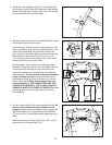
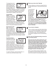
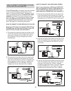
4. See step 6 and locate the four Upright Bolts (86). Loosen
the Upright Bolts two to three turns.
See drawing 4c. With the help of a second person, hold
the Console Base (101) near the Uprights (80, 84). Look
under the Console Base and locate the wires on the
sides of the Console Base. Make sure that the wires are
not routed through the openings for the Trays (109,
111). Drawing 4a shows the correct route for the wires.
Drawing 4b shows an incorrect route.
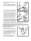
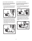
See drawing 4c. Cut the plastic ties holding the Wire
Harness (74) and the pulse wire in the Uprights (80, 84).
Connect the Wire Harness and the pulse wire to the
wires on the sides of the Console Base (101) (see the
inset drawings). The connectors should slide together
easily and snap into place. If the connectors do not
slide together easily and snap into place, turn one con-
nector and try again. Make sure to connect the con-
nectors properly. IF THE CONNECTORS ARE NOT
CONNECTED PROPERLY, THE CONSOLE MAY BE
DAMAGED WHEN THE POWER IS TURNED ON. Insert
the excess
Wire Harness and pulse wire up into the
Console Base.
101
111
109
80
84
77
4a
4b
4c
Correct
Incorrect
Pulse
Wire
74