


8
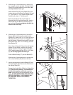
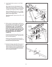
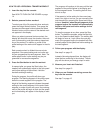
6. With the help of a second person, hold a Bolt
Spacer (80) inside the lower end of the Left
Upright (74). Insert a 3/8" x 4 1/2" Bolt (6) with a
3/8" Star Washer (9) into the Left Upright and
the Bolt Spacer. Repeat this step with a second
Bolt Spacer (80), 3/8" x 4 1/2" Bolt (6), and 3/8"
Star Washer (9).
Orient the Left Upright (74) and the Left Upright
Spacer (76) as shown. Hold the Left Upright
Spacer and the Left Upright against the Base
(83). Partially tighten the two 3/8" x 4 1/2" Bolts
(6);
do not fully tighten the Bolts yet.
Press a Base Endcap (77) into the Base (83).
With the help of a second person, tip the tread-
mill so that the Base (83) is flat on the floor.
76
74
6
83
80
80
77
9
6
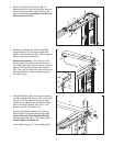
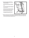
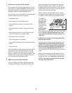
5. With the help of a second person, carefully tip
the treadmill onto its right side. Partially fold the
Frame (56) so the treadmill is more stable; do
n
ot fully fold the Frame yet.
A
ttach a Base Pad (81) to the Base (83) in the
location shown with a Base Pad Spacer (13) and
a 1" Tek Screw (2). Then, attach another Base
Pad (81) with only a 1" Tek Screw (2).
Remove the 3/8" Nut (8) and the 3/8" x 2"
Shoulder Bolt (32) from the Base (83). Attach a
Wheel (84) with the Bolt and the Nut that you
just removed. Do not overtighten the Nut; the
Wheel must turn freely.
5
83
84
56
32
8
81
2
81
13
2
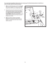
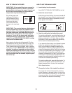
7.
Have a second person hold the Bridge (95) near
the Right Upright (78).
Remove the wire tie from
the Upright Wire (38).
Connect the Upright Wire (38) to the Bridge Wire
(52). See the inset drawing. The connectors
should slide together easily and snap into
place. If they do not, turn one connector and try
again. IF THE CONNECTORS ARE NOT CON-
NECTED PROPERLY, THE CONSOLE MAY
BE DAMAGED WHEN THE POWER IS
TURNED ON.
78
95
52
Wire Tie
7
38
38
52