


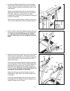
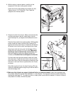
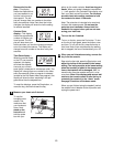
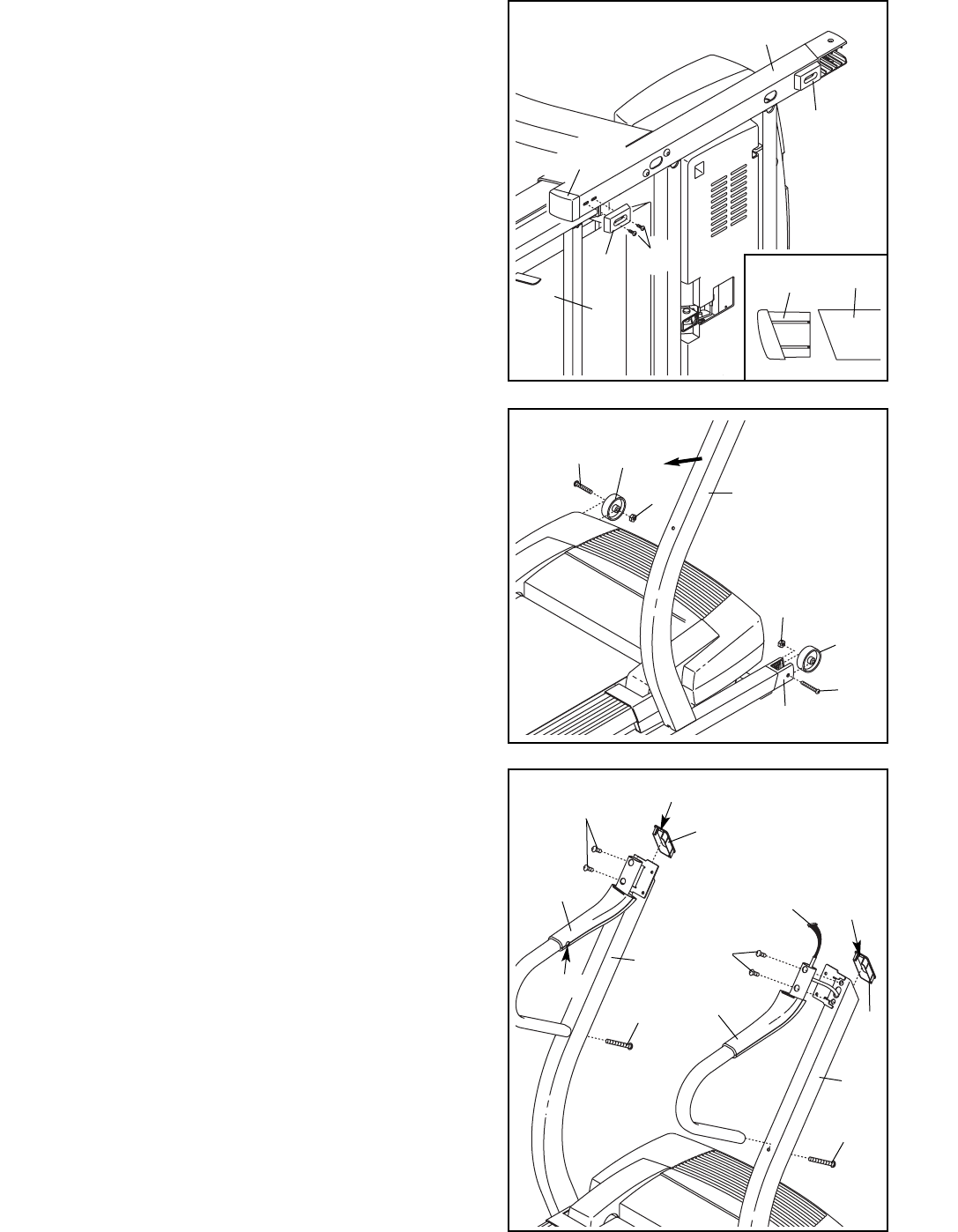
2. Press the two Base Endcaps (99) (only one is shown)
into the Base (109). Make sure the angle of each Base
Endcap matches the angle of the Base, as shown in the
inset drawing.
Attach the two Base Pads (100) (only one is shown) to
the bottom of the Base (109) with four 3/4” Tek Screws
(47). Note: There are no screw holes in the Base
Endcaps (99). Press firmly on the screwdriver when tight-
ening the Tek Screws.
With the help of a second person, carefully tip the tread-
mill so the four Base Pads (100) are resting on the floor.
2
100
109
100
21
47
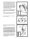
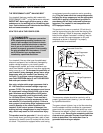
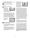
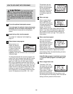
4. Identify the left handrail, which has a hole in the indicated
location, and the right handrail. Hold the right handrail
near the Right Upright (82). Insert the Wire Harness (83)
into the large hole in the right handrail and out of the
upper end as shown.
Next, hold the right handrail against the Right Upright (82),
and hand tighten a 4” Bolt (112) into the Right Upright and
the lower end of the right handrail. Tighten two 5/16” x 1”
Bolts (122) into the upper end of the right handrail and
the Right Upright. Be careful not to drop the Bolts into
the handrail. Firmly tighten all three Bolts.
Attach the left handrail to the Left Upright (81)as de-
scribed above. Note: There is not a wire harness in the
Left Upright.
Press two Upright Endcaps (69) into the upper ends of
the Uprights (81, 82). Make sure that the notches in the
Upright Endcaps are up as shown.
4
82
81
83
Notch
Notch
69
69
122
122
Left
Handrail
Right
Handrail
Hole
112
112
99
109
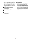
3. Attach a Wheel (108) to each Wheel Housing (106) (only
one is shown) with a Wheel Bolt (107) and a Wheel Nut
(21). Make sure that the Wheel Bolts are inserted
from the sides shown. Do not overtighten the Wheel
Bolts.
3
107
106
108
21
82
21
107
108
7
99