


11
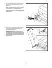
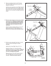
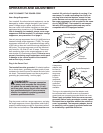
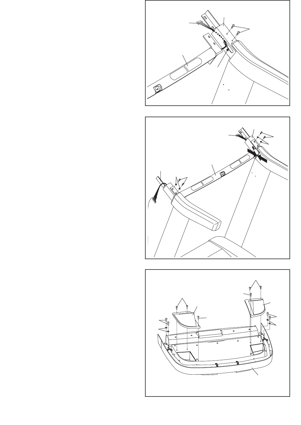
9. Remove and discard the #10 x 3/4" Screws
(3) from the Right Handrail (93) and the Left
Handrail (not shown).
Hold the pulse assembly near the Right Handrail
(93). Insert the pulse wire from the pulse assem-
bly into the hole in the side of the Right Handrail
and pull it out of the end of the Right Handrail as
shown.
93
Hole
Pulse Wire
9
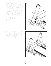
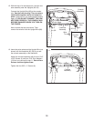
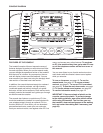
10. Slide the pulse assembly onto the Left and Right
Handrails (92, 93). Make sure that the brack-
ets on the pulse assembly are ush against
the rubber on the Handrails. Be careful not
to pinch the pulse wire against the pulse
assembly.
Attach the pulse assembly with four #10 x 3/4"
Screws (3) and four #10 Star Washers (11).
Start all four Screws, and then tighten them.
10
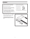
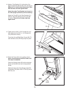
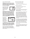
11. Set the console assembly face down on a soft
surface to avoid scratching the console
assembly.
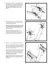
Identify the Left and Right Trays (110, 111).
Attach the Trays (110, 111) to the console
assembly with six #8 x 1/2" Screws (1). Start all
six Screws, and then tighten them. Be care-
ful not to overtighten the Screws.
Remove the four 5/16" x 5/8" Screws (4) and
5/16" Star Washers (12) from the console
assembly. They will be used in step 13.
1
1
4
4
Console
Assembly
1
110
111
1
12
12
11
3
3
11
Pulse
Assembly
3
11
92
93
Pulse
Assembly
Pulse Wire