


8
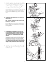
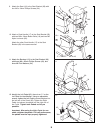
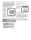
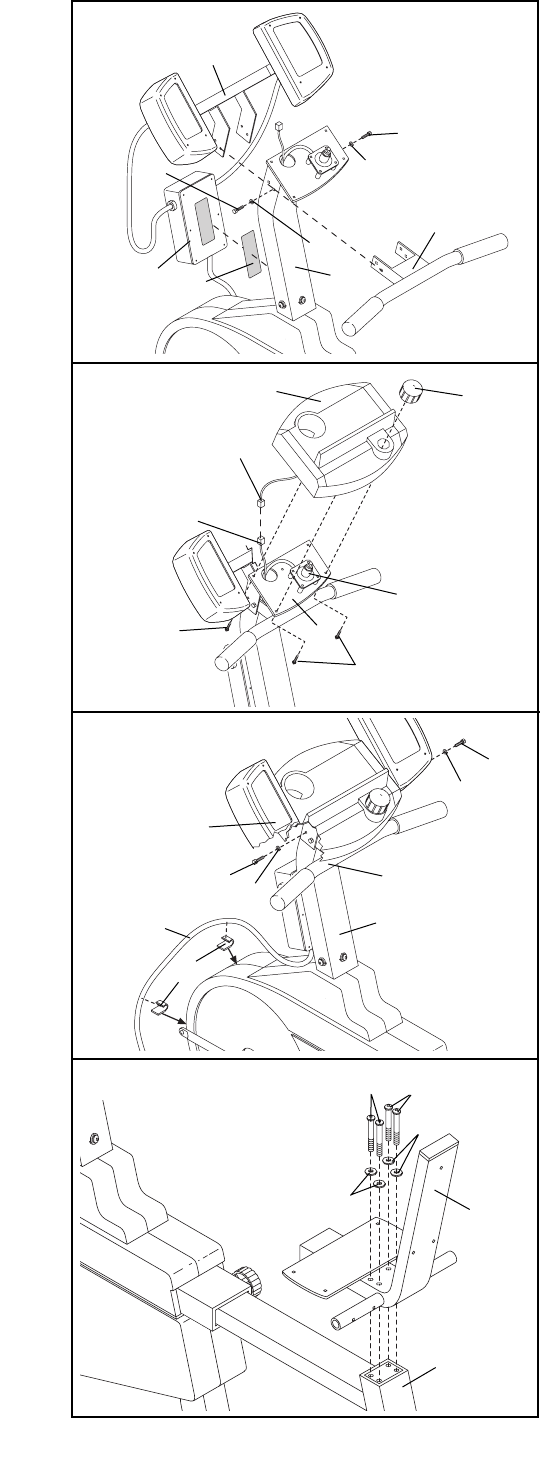
7. Finish attaching the Handlebar (4) and the Light
Frame (82) to the Upright (2) with two more M6 x
25mm Hex Head Screws (14) and two more M6
Split Washers (67). Tighten all four Hex Head
Screws.
Remove the backing from the Cord Clips (95) and
press them onto the Light Cycle in the indicated
locations. Insert the Power Cord (73) into the Cord
Clips. Make sure that the Power Cord cannot get
caught on the pedals while you are exercising.
8. Attach the Seat Bracket (69) to the Seat Frame (3)
with four M6 x 48mm Button Bolts (70) and four M6
Flat Washers (34).
69
3
70
34
34
70
8
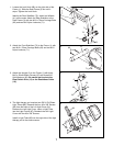
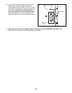
6. Connect the Reed Switch Wire (13) to the wire on
the Console (8).
Next, attach the Console (8) to the Upright (2) with
four #8 x 5/8Ó Screws (22).
Press the Resistance Knob (9) onto the Resistance
Control (10). Be sure that the mark on the Knob is
correctly aligned.
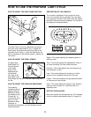
5. Attach the Handlebar (4) and the Light Frame (82) to
the Upright (2) with two M6 x 25mm Hex Head
Screws (14) and two M6 Split Washers (67), but do
not tighten the Screws yet. Make sure that the
Screws are in the indicated holes. Note: Two
more Screws will be attached in step 7.
Remove the backing from the Fastener Strip (77) and
press it onto the Upright (2) in the position shown.
Firmly press the Ballast Box (81) onto the Fastener
Strip.
2
14
14
82
67
67
77
81
4
5
Console
Wire
10
8
9
13
2
22
22
14
14
2
4
67
67
95
73
82
7
6