7
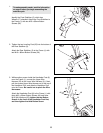
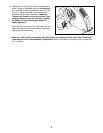
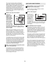
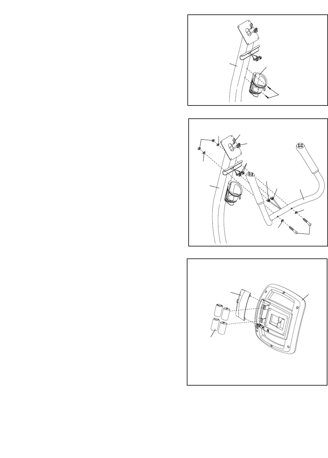
4. Attach the Water Bottle Holder (18) to the
Handlebar Post (6) with two M4 x 19mm
Screws (33).
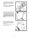
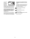
6. The Console (9) requires four 1.5V “D” batteries
(not included); alkaline batteries are recommended.
Press the tab on the battery cover and remove the
battery cover. Next, insert four batteries into the
Console. Make sure that the batteries are orient-
ed as shown by the diagram inside the battery
compartment. Then, reattach the battery cover to
the Console.
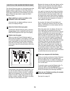
Note: The Console (9) can be operated with an
optional power supply instead of batteries. To pur-
chase a power supply, call the telephone num-
ber on the front cover of this manual. Plug one
end of the power supply into the jack on the con-
sole. Plug the other end of the power supply into an
appropriate outlet that is properly installed in accor-
dance with all local codes and ordinances.
4
6
18
33
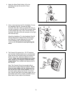
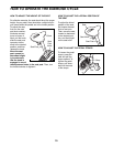
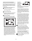
5. Have a second person hold the Handlebar (7) near
the Handlebar Post (6). Connect the Right
Controller Wire (65), which is marked with a tag, to
the right connector on the Split Wire Harness, which
is also marked with a tag. Then, connect the Left
Controller Wire (54) to the left connector on the Split
Wire Harness (25).
Attach the Handlebar (7) to the Handlebar Post (6)
with two Black M10 x 50mm Button Screws (64),
two Black M10 Curved Washers (61), two M10
Curved Washers (36), and two M10 Nylon
Locknuts (48). Be careful to avoid pinching the
wires.
5
48
36
55
25
25
61
61
54
65
7
6
64
36
6
Battery
Cover
Batteries
9


