


7
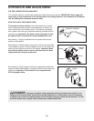
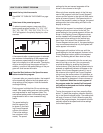
4.
Orient the Latch Housing (73) so the large hole is on the
indicated side. Attach the Latch Housing to the left
Upright (84) with two Screws (3); start both Screws be-
fore tightening either of them.
Remove the knob from the pin. Make sure that the collar
and the spring are on the pin. (Note: If there are two col-
lars, place one on each side of the spring.) Next, insert
the pin into the Latch Housing (73). Then, tighten the
knob back onto the pin.
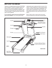
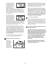
Plug in the power cord as described on page 10, and
turn on the power as described on page 12. Note: The
treadmill may automatically rise to the maximum incline
level and then return to the minimum level.
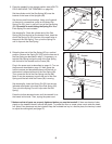
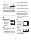
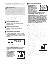
3. Insert the Wire Harnesses (77, 78) down into the right
Upright (84).
Set the console assembly on the Uprights (84). Be care-
ful to avoid pinching the Wire Harnesses (77, 78).
While a second person holds the console assembly, at-
tach it with four Console Bolts (64) and four Star Washers
(8) as shown; start all four Console Bolts and then
firmly tighten them.
Console
Assembly
64
77, 78
64
8
8
84
84
3
84
77
78
2
Console
Assembly
77
78
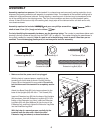
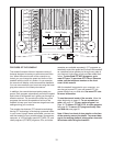
2. With the help of a second person, carefully raise the
Uprights (84) to a vertical position.
Have the second person hold the console assembly near
t
he Uprights (84) as shown. Look under the console as-
sembly and locate the Console Wire Harness (78).
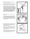
Remove the tie securing the Upright Wire Harness (77) to
the right Upright (84). Next, connect the Upright Wire
Harness to the Console Wire Harness (78). Make sure to
connect the connectors properly (see the inset draw-
ing). The connectors should slide together easily and
snap into place.
If the connectors do not slide together
easily and snap into place, turn one connector and then
try again.
IF THE CONNECTORS ARE NOT CON-
NECTED PROPERLY, THE CONSOLE MAY BE DAM-
AGED WHEN THE POWER IS TURNED ON.
3
Pin
Spring
Collar
Knob
73
4
84
Large
Hole